| Applies To | |||
| Product(s): | Microstran | ||
| Version(s): | V8i | ||
| Environment: | N/A | ||
| Area: | User Interface | ||
| Original Author: | Richard Collins | ||
Extrusion
There is a check box in each of the Linear Copy, Polar Copy, and Reflect dialog boxes for "Extrude nodes". When you perform a copy operation you may "extrude" each copied node into a series of members - in other words, there will be a string of new members lying on the path traced out by each node involved in the copy operation. The member x axis is aligned with the direction of extrusion.
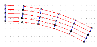
Extrusion is a powerful feature that enables you to create many types of structure with minimal effort. For example, you can make a curved bridge deck model by drawing a member representing a cross-beam at one end, sub-dividing it as required to create a node at the location of each girder, and then performing a polar copy with extrusion. There will be a new cross-beam, together with connected girders (longitudinal) for every copy.

The red members are extruded.
What's the Use of the Grid When Most Nodes Are Not on a Grid Point?
Even if you do not need to snap to grid points when drawing members, you may find it provides a useful frame of reference for viewing nodes. In oblique views it also provides a visible representation of the drawing plane. If your structure is based on a rectangular grid, you may change the grid spacings to match the structure grid.
Usually, at an early stage during the graphical input of a structure, you will find that you begin to use copy operations instead of drawing one member at a time. At this stage, you will probably also find that the grid is rarely required and that most drawing operations use Mid/End snap mode.
How Can I Input Nodes that Are Not on a Grid Point?
During a drawing operation (i.e. after you select the pencil tool), you establish a new node every time you click the left mouse button. However, you may also type node coordinates at the keyboard. As soon as you enter a keystroke, Microstran displays a dialog box in which the numerical input is shown. You complete the numerical input by pressing Enter or clicking the OK button in the dialog box.
With this method, you may conveniently enter nodes which are not on a grid point. X, Y, and Z coordinate values may be entered into the dialog box but if the Z, or Y and Z coordinates are zero you do not have to enter them. Relative coordinates (offsets from the previous node) are easily entered at the keyboard. Just type "R" or "r" or "@", and the following values will be interpreted as offsets from the previous node.
Load Sub-division
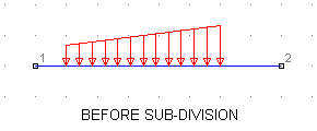
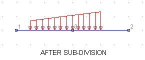
You may make changes to a job after the loads have been input without worrying about member loads "migrating" to other members or disappearing altogether. If a loaded member is sub-divided (by connecting a new member to its mid-point, for example), each part of the original member will become a new member and the original loads will be automatically split, if necessary, between the two new members.
 |  |