| Applies To | |
| Product(s): | AutoPIPE |
| Version(s): | ALL; |
| Area: | Modeling |
| Date Logged & Current Version | Sept 2022 12.08.01.010 |
Problem:
How to model a Pipe clamp shoe guide support using AutoPIPE?
Solution:
Before modeling a support, one should take some time to evaluate the criteria required and write down all requirements and assumptions.
Example,
Which directions are restrained? - Answer: The pipe clamps and shoe can assumed to be rigidly connected. Support restrained directions are: cannot move down, limited lateral and vertically up movement allowed .
What stiffness are going to be applied in all directions? - Answer: should it be assumed to be rigid (see Edit model options dialog for rigid pipe / support stiffness settings), or to enter in more realistic values.
Should a simplified approach or detailed approach be used? - Answer: user must decide if a simplified approach is suitable or if a more detailed approach is needed.
Another words, should the most detailed modeling approached be used or just use a simplified support that good enough for pipe stress analysis purpose.
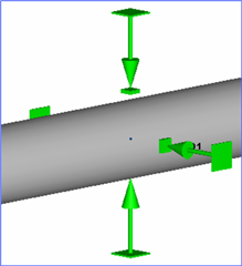
Approach #1: Simplified support
The simplest modeling approach would just be a single Guide support. This meets all of the requirements for this support. However, be mindful that a guide support only allows one spring stiffness setting. One may consider modeling with 2 incline supports, where each incline support can have a different stiffness setting.
Select the pipe node point where the pipe shoe is to be inserted, and insert a Guide support
Configure support settings as needed.
 or
or 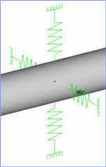
If support is to be combined with a Line stop or allowed a limited amount of axial movement, then inset a single Line Stop support with the proper settings.
Note, one may consider using an incline support instead of a Line stop. An Incline support has the same capabilities and much more than a Line stop support.
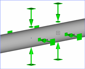
Approach #2: Simplified support
A little more involved support would include the 2 supports, one on each end of the pipe shoe.
Select the pipe node point where the pipe shoe is to be inserted, and insert a Guide support
At the other end of the pipe shoe, insert a corresponding node point, and insert the 2nd Guide support
Configure support settings as needed.
 or
or 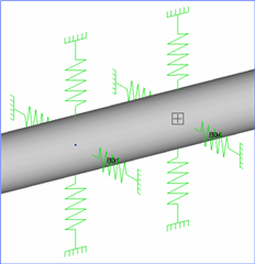
If support is to be combined with a Line stop or allowed a limited amount of axial movement, then inset a single Line Stop support with the proper settings.
Note, one may consider using an incline support instead of a Line stop. An Incline support has the same capabilities and much more than a Line stop support.
Approach #3: Detailed support
Again a little more involved support would include taking the steel pipe shoe itself into consideration.
Start by inserting the steel properties of the pipe shoe.
Next select the pipe node point where the pipe shoe is to be inserted, and locate the starting point of the Steel which is center to center distance below the pipe.
Insert Steel member equal to the length of the shoe.
To rigidly connect the pipe to the pipe shoe, insert a Node link at each clamp point(ex. Node link at B01 connected to Beam at M01, and Node link at B04 connected to M02)
Next model the pipe shoe support. Typically a pipe shoe is either continuously supported or only supported across the face of a beam. Thus allowing the pipe shoe to move freely on the horizontal plane. Therefore one could model additional steel beams, however for this modeling approach just use a single v-stop in the middle of the pipe shoe to represent the shoe resting on a single beam face.
If support is to be combined with a Line stop or allowed a limited amount of axial movement, then inset a Incline support on the pipe shoe and connect the support to the Ground or other steel structure as needed.
Note, a Line stop support cannot be inserted on a beam, however an Incline support has the same capabilities and more than a Line stop support.
Done:
Notes:
1. Because the pipe shoe is not connected to additional structural steel a very flexible anchor must be added to one pipe shoe node point to avoid the dreaded E801-1: FATAL ERROR : Unstable system message from appearing.
2. Again, users could always model the complete beam structure inside of AutoPIPE.
3. Recall AutoPIPE use simple Beam element center-line based theory, therefore everything in AutoPIPE is connected at the centerline of the object. There is no surface to an object in AutoPIPE, it is just a 3d graphic representation.
4. To create a surface connection point, model a rigid weightless member from the center line of an object to it's surface, and connect objects to that surface point. For an example, see the following AutoPIPE help section: Help > Contents> Contents Tab> Modeling Approaches> Modeling Approaches> Vessel