We are pleased to announce that ProStructures CONNECT Edition Update 5 (10.05.00.54) is now available on Software Downloads and for update through the CONNECTION Client.
What`s New Highlights
ProStructures
Configuration
- For ProStructures CONNECT Edition Update 5 configuration refer to ProStructures CONNECT Edition Update 2 Configuration Setup Guide,the Setups for ProStructures CONNECT Edition Update 3,4 and 5 are done identical.
- Here, you will find more about:
- Basic information about CONNECT Edition configuration
- What changed moving from V8i WorkSpaces to the CONNECT Edition Configuration
- How to work with the new setup
- Customization beyond what is delivered in ProStructures
ProjectWise
- ProStructures CONNECT Edition Update 5 is compatible with
- ProjectWise CONNECT Edition Update 3.1 (10.00.03.140),
- ProjectWise CONNECT Edition Update 3.1 Refresh (10.00.03.167),
- ProjectWise CONNECT Edition Update 3.2 (10.00.03.262), Update 3.3 (10.00.03.280)
- For complete compatibility metrics for design, modeling products see ProjectWise Version Support Matrix
Structural Synchronizer
- ProStructures CONNECT Edition Update 5 is compatible with Structural Synchronizer CONNECT Edition V11 (11.00.03.04) & V11 Update1 (11.01.02.09).
Please Note: The Structural Synchronizer version 11.01.01.04 is not supported.
DgnDB iModel Importer
- ProStructures CONNECT Edition Update 5 is compatible with iModel publishing 1.6
- ProStructures CONNECT Edition Update 5 is compatible with iModel publishing 2.0
Resolved Issues
Enhancements
ProStructures Properties can be added to Item Types as expressions in the Item Type expressions dialog.
- ISM
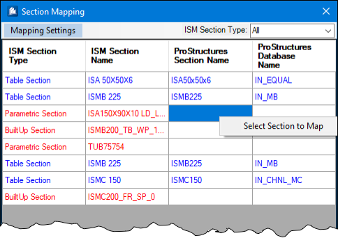
- ISM Section Type filters added to the Section Mapping dialog to narrow the list of sections displayed.
- Categorization of Shape Types is added in the Section Mapping dialog so that the information about the ISM shape types in the mapping table can be used to choose the appropriate shapes.
- Welded Shapes are added to the mapping table for mapping ISM sections with welded shapes in ProStructures. You can create welded shapes in ProStructures in advance to use for mapping during import.
- Combined Shapes are added to the mapping table for mapping ISM sections with combined shapes in ProStructures. You can create combined shapes in ProStructures in advance to use for mapping during import.
- Custom Sections are added to the mapping table for mapping user defined sections with sections available in ProStructures while importing ISM files instead of creating sections on the fly.
- Built-Up Sections are added to the mapping table for mapping built-up sections with sections available in ProStructures while importing ISM files.
- Parametric Sections are added to the mapping table for mapping parametric sections with sections available in ProStructures while importing ISM files.
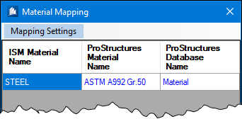
- Material Mapping dialog is now displayed during every import.
- Dataset Changes:
- Additional steel and concrete material definitions included in Russia workspace. Please check ‘ProStructuresMaterial.mdb’ located at \WorkSpaces\Russia\Standards\ProStructures\Data.
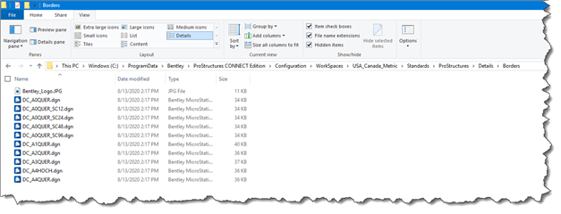
- Redefined path for border files in US_Canada Imperial and Metric workspace. Now border frame files are accessed from \WorkSpaces\USA_Canada_(UnitSystme)\Standards\ProStructures\Details\Borders.
- New border files are added to US_Canada Imperial workspace, with attractive title blocks.
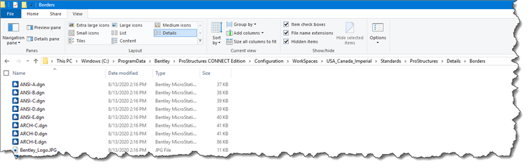
- 'Detail Center Express' templates have been added as favorites for ANSI and ARCH border files in US_Canada Imperial workspace.
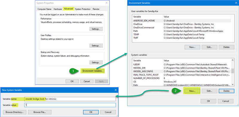
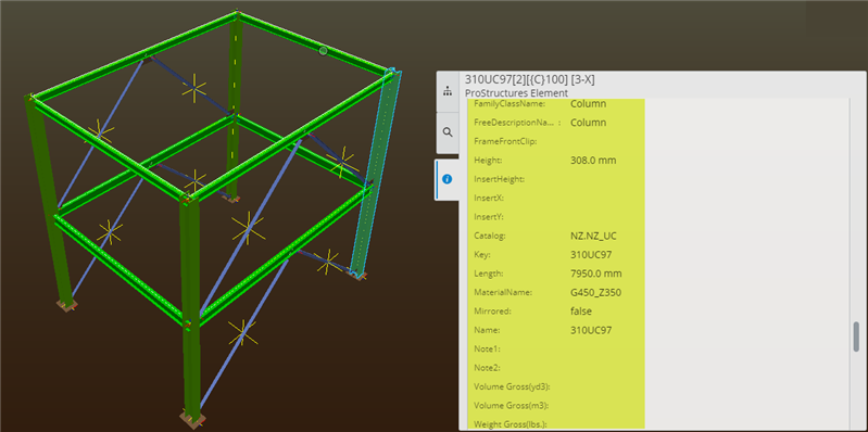
- Export PS Properties to iModel Hub
- Now PS Properties can be exported to iModel Hub or iTwin Design Review by adding one Environment System variable into the system.
The variable is imodel-bridge-look-for-intrinsic and the value will be 1
ProSteel
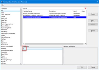
- Features moved from Technology Preview to Commercial Release
The following feature that were in Technology Preview mode in previous updates, have been commercially released in this update:
- Merge into Master is now working (PS_disable_referencemerge) needs to be set to 0
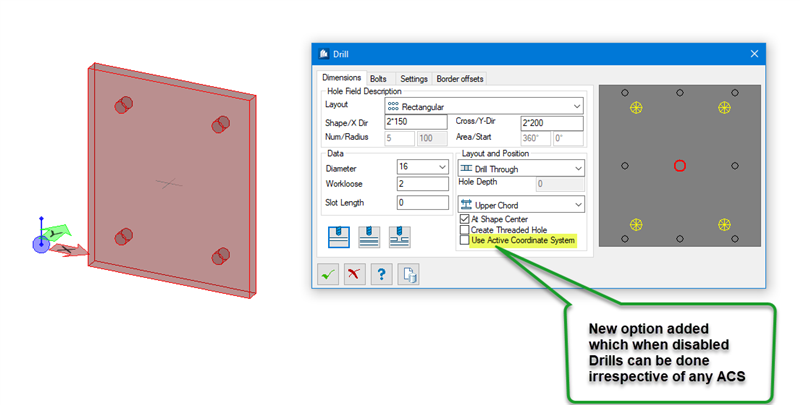
- Steel Parts Drilling Improvement
Steel Parts i.e. Shape, Flat and Plate now can be automatically drilled in the thickness direction irrespective of ACS. There is no more necessary to set ACS before drilling.
- Positioning Improvements:
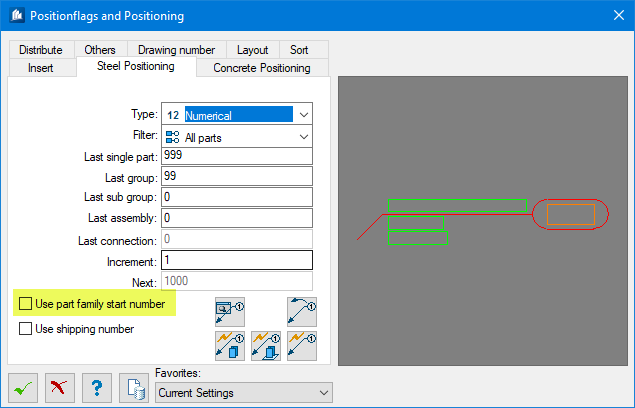
- More control over positioning start numbers and ranges based on part family assignments. One can define range for position numbers e.g. First floor beams can start from 1000 and second floor beams can start from 2000 etc.
- New Column Added in Part Families Dialog for Position Start Numbering
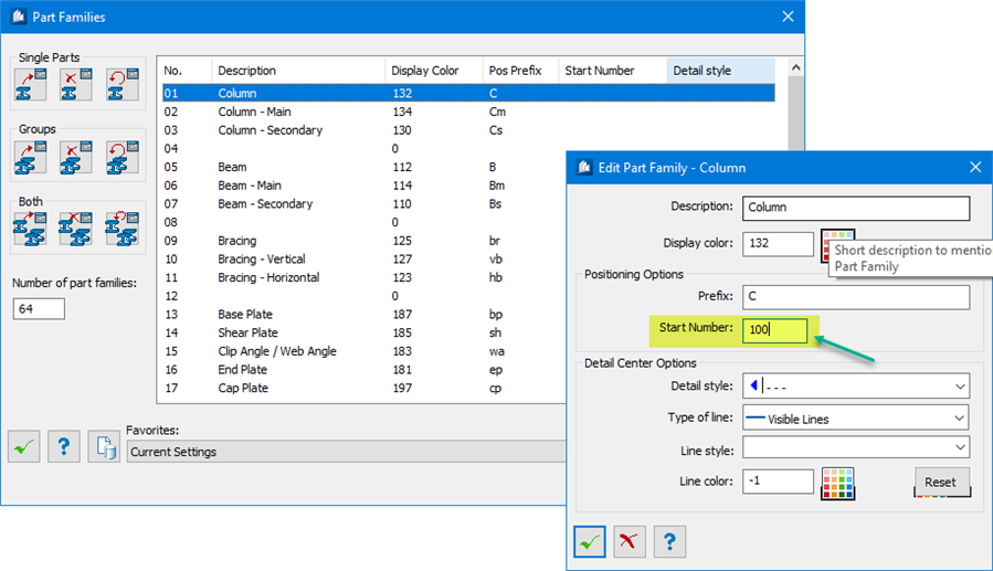
- Added new option “Use part family start number” to get the Position No according to Part family Start No.
- ProSteel group as IFC Assembly
Now ProSteel groups are exported as IFC Assemblies in IFC Export. This will be helpful to recreate the hierarchy of elements in another software like StruMIS.
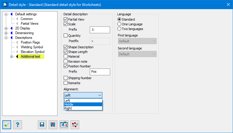
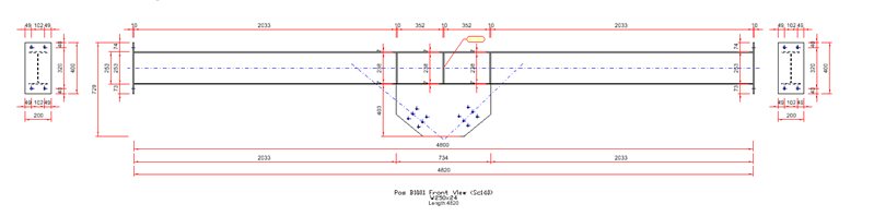
- Added 2D Detail Description Text Alignment Options
Now 2D detail description can be aligned Left, Center and Right to as required with newly added options from detail style.
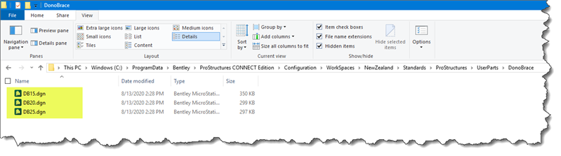
- Added Dono Brace as User Part
Dono Brace has been added as a User Part in NewZealand Workspace.
- [Technology Preview] OpenTower Integration
3D model from OpenTower can be now imported to ProSteel. OpenTower creates an .xml output and this xml file can be imported to ProSteel. Currently, import can be run using key-in “prosteel import opentower’”. Following implementation has been done so far…
- XML Integration with ProStructures Tower Classes provides the import mechanism to work with the latest XML file format.
- Workframes created for imported tower and elements that need to be assigned to different display classes so drawings can be created effectively using the model.
- Tables can now be created in the model containing Tower parametric data to use in drawings.
- Mapping of Standard SPC Sections from XML to ProStructures.
- Un-Mapped Sections generated are as dummy members and highlighted red so changes can be made to them later.
- The feeder lines in the plan view can be scaled with a bigger scale than the tower so that the feeder lines are better visible in the drawing.
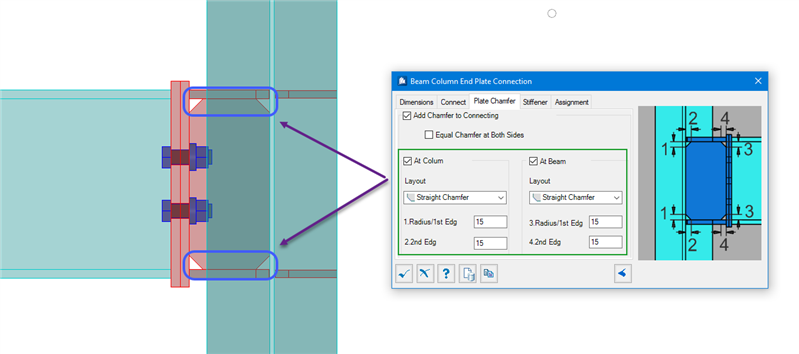
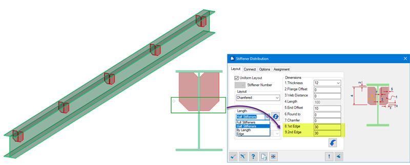
- Connections:
- Beam to Column End Plate connection enhanced with chamfer option on vertical Stiffener.
- In Stiffener distribution tool triangular stiffener is now have square end in place of sharp vertex.
- StruMIS Integration (IFC)
The properties necessary for StruMIS can be exported in an IFC file exported from ProStructures to manage fabrication using StruMIS effectively.
-
Improved Part Families User Interface
The Part Families dialog box is now re sizable and easier to use.
- Improved Plate Chamfer Tool
A new Swap Values option is added to the Plate Editor and Element Modification dialogs' Chamfer tab. Clicking the Swap Values button swap the chamfer direction on plates by switching the values you enter for the first and second chamfer distances.
- Improved Handrail Tool
The Standard Handrail tool can now be used with Line and Smart Line elements.
- Group Selection Improvement
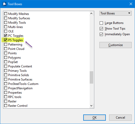
A new PS Toggle Enable Select Group as Whole allows you to select whole groups or individual elements within groups in the Named Groups dialog.
- OpenBuildings Designer Integration
OpenBuildings Designer integrates ProStructures elements into its Structural workflows for more detailed modeling options.
- [Technology Preview] Pre-Engineered Building Component Placement.
This is work-in-Progress feature and can be enabled by setting configuration variable value PS_ENABLE_PEBMEMBERS =1. Later, re-start the session and run key-in “prosteel peb straightmember” to place PEB shape.
- Add-ON
See Video:
Summary of some of the features of ProSteel
www.youtube.com/watch
ProConcrete
- [Technology Preview] AutoLabels for 2D rebar drawings
New feature, AutoLabels introduced which has ability to add Bar labels automatically while creating 2D Rebar drawing.
Note: The Autolabel feature is enabled by default if the Technology Preview feature "AutoLabels for 2D Rebar Drawings" option is toggled ON during the installation.
www.youtube.com/watch
- Rebar Selection Improvement
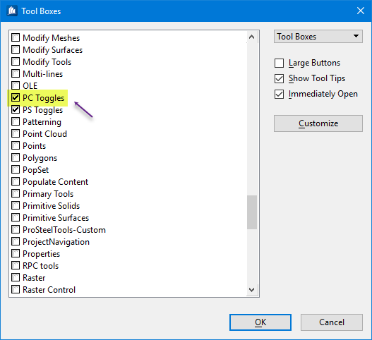
New PC Toggles give you greater control over Rebar selection when Item Types are being assigned, and can be used as a review method, for understanding how Rebar Sets are built in the model. PC Toggles select either a Rebar Set, a Rebar Assembly or an individual Rebar Element. This can be activated from Tool boxes at File > Settings > User > Tool Boxes
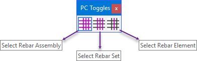
Note: Other functionality like double clicking on the bars or opening the bars PS Properties edit the whole assembly, regardless of which PC Toggle is activated.
-
2D Support for Vary Set Bar and Fanned Bar Ranges
An enhancement in 2D drawings such as plans and elevations, allows Vary Set Ranges and Fanned Bar Ranges created using the Irregular Dispatch tool to be properly displayed.
- 2D Support for Curved Bar Ranges
An enhancement in 2D drawings such as plans and elevations, allows Arc Bar Ranges to be properly displayed. In sections, where curved bars are cut, the bars are now properly re symbolized as circles.
- Improved Rebar Tags
Tags added at the end of main bars to indicate their location are enhanced with improved presentation and text alignment based on their position against the bars.
-
[Technology Preview] Improvements for Drawing Schedule Generator
The Rebar Schedule Generator tool is enhanced for:
- Improved performance when loading rebar data,
- Zone column added to display data like Near Face, Far Face, Top, Bottom,
- Label column added to display data like X or Y direction as well as Remarks from reinforcement placement dialogs,
- Item Type column added to display data from user defined Item Type properties assigned to rebar,
- The ability to hide unused columns in the Custom Schedule is added which is especially useful with Bend Dimensions, and
- The ability to create In-line Bar Weight Summaries.
-
[Technology Preview] Improvements for Manual Bar Marking Tool
Improved performance when loading rebar data into the (Technology Preview) Manual Bar Mark Manager tool.
-
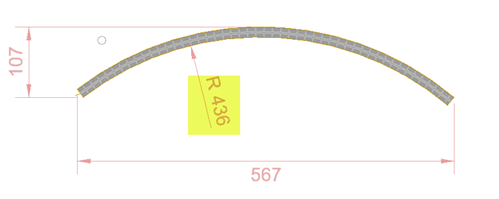
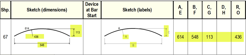
Shape Code 67 dimensions are not coming as per Rebar Shape Code BS8666:2005
Radius dimension is now measured from inner side of bar. Also added B and C dimensions for Shape 67
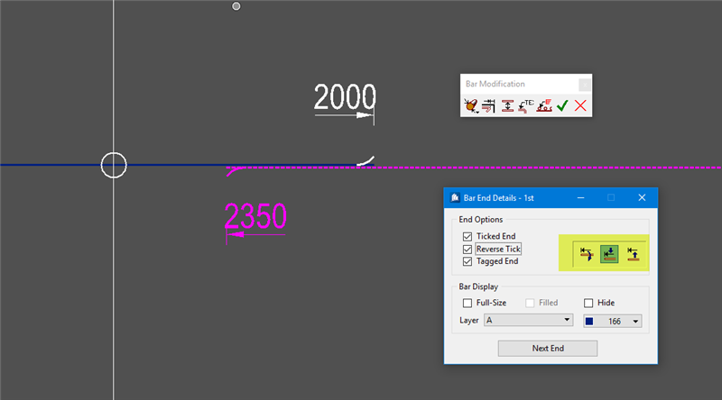
- Edit End Conditions Dialog Box Cleanup
Cleaned up Edit End Condition dialog by removing repeated End condition edit options. Now user can apply End Condition by RebarSet instead of Zone which will provide user more control
-
Added “Dual bar” display and Label Option
Dual Bar option has been added to display Range bar as two bars only at each end of rebarset on 2D Rebar Drawing and delimiter also fit to them.
- First two and Last two typical bars can be shown for Bar range.
- First two and last two long bars can be shown, and topline label can be added to it accordingly.
- Added dual in Leader line which is at angle 45 degree and added topline connecting all leader. label can be added to center of topline.
-
Added Drag & Drop Functionality to adjust Delimiter location
- When ILBL = 0, The existing Adjust delimiter controls will start Move Delimiter functionality
- When ILBL is not equal to 0, The existing delimiter adjust control works as previous.
Note: Previous when ILBL = 0 , The step size is 0.5 mm
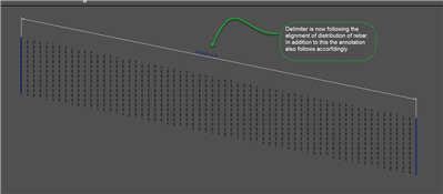
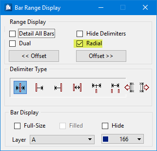
- Improvements in Delimiter and label settings
- Delimiter now follows the distribution of Rebar path
Now Delimiter is following the Rebar distribution path when path even inclined or in some angle. New Range Display "Radial" is added. By enabling this option in Bar range Display you can now able to achieve delimiter even in distribution path
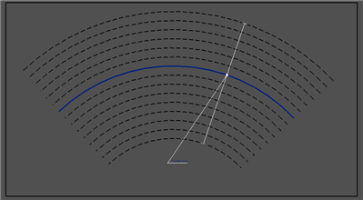
- Curved delimiter is now possible
You can now provide curved delimiter and the delimiter end also follows the curvature.
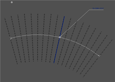
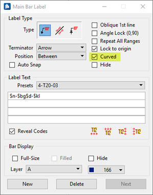
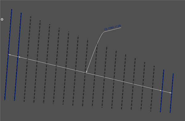
- Introduced Curved Label
Now Curved Labels can be shown.
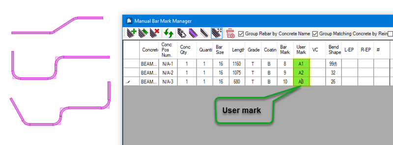
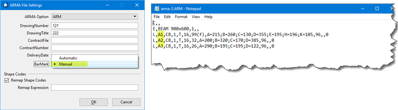
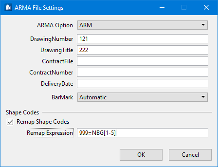
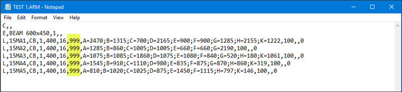
- Export User Mark to ARMA
Now User Bar Marks can be exported to ARMA.
- Re-Mapping of Un-managed rebar shapes during ARMA export
For unmanaged shape named as NSD 1, NSD 2 or NSD 3 to be converted to NSD only for ARMA Export machine.
-
Mechanical device Start & End swapping
In Partlist, Mechanical Device will be tabled in Start and End to match with rebar shape sketch Start and End.
Now while reinforcing beam, if solid columns is supporting that beam then those solid will be identify as support and will be highlighted in red and green color as like concrete columns.
- Create Concrete Solid Reference Object on User defined level
Previously, Concrete reference object was getting created on active level, user has to manually change the level to desired level.
This inconvenience has been addressed by introducing the new configuration variable which sets user defined level for Concrete solid reference object.
If User defined level is not set then instead of active level, now Concrete Solid Reference object will get created on PC_CONCRETE level.
How to use this feature:
1. Open the configuration variable dialog
2. Set new variable,
Variable name: PC_OVERLAY_LEVEL
Value – Level name (Put the level name on which CSR should get created.)
See Video:
Summary of some of the features of ProConcrete
www.youtube.com/watch