RAM Elements 2025 (v.25.00.02.196) Release Notes – Updated October 2025
Features:
1. Update Concrete Design to ACI 319-25. This release updates RAM Elements to support the ACI 319-25 design standard for beams, columns, footings and walls, providing engineers with the latest concrete design provisions.
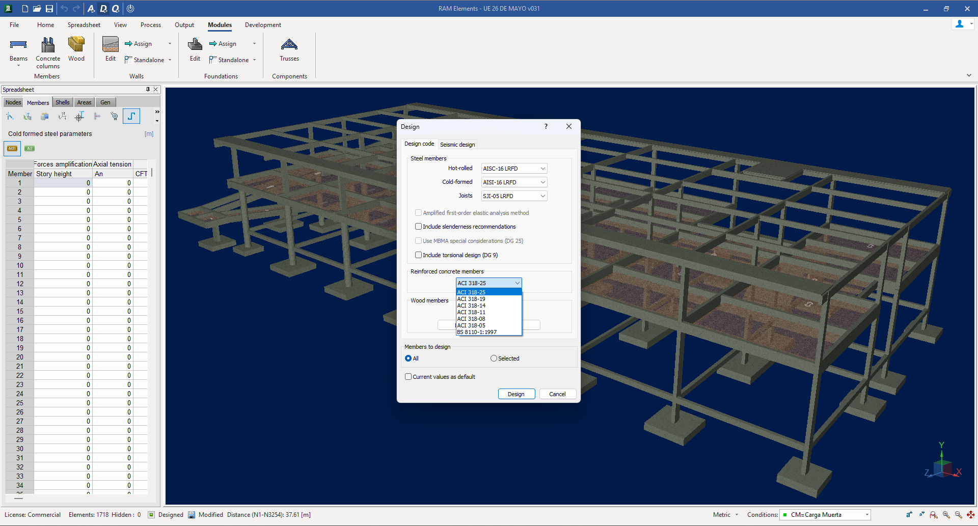
Figure 1. New ACI 318-25 concrete design code
The update includes to following:
- RAM Elements Preliminary Design.
- Continuous Beam, Beam Design and Concrete Column modules.
- Footing Design module
- Retaining Wall, Concrete Wall and Tilt-up Wall module.
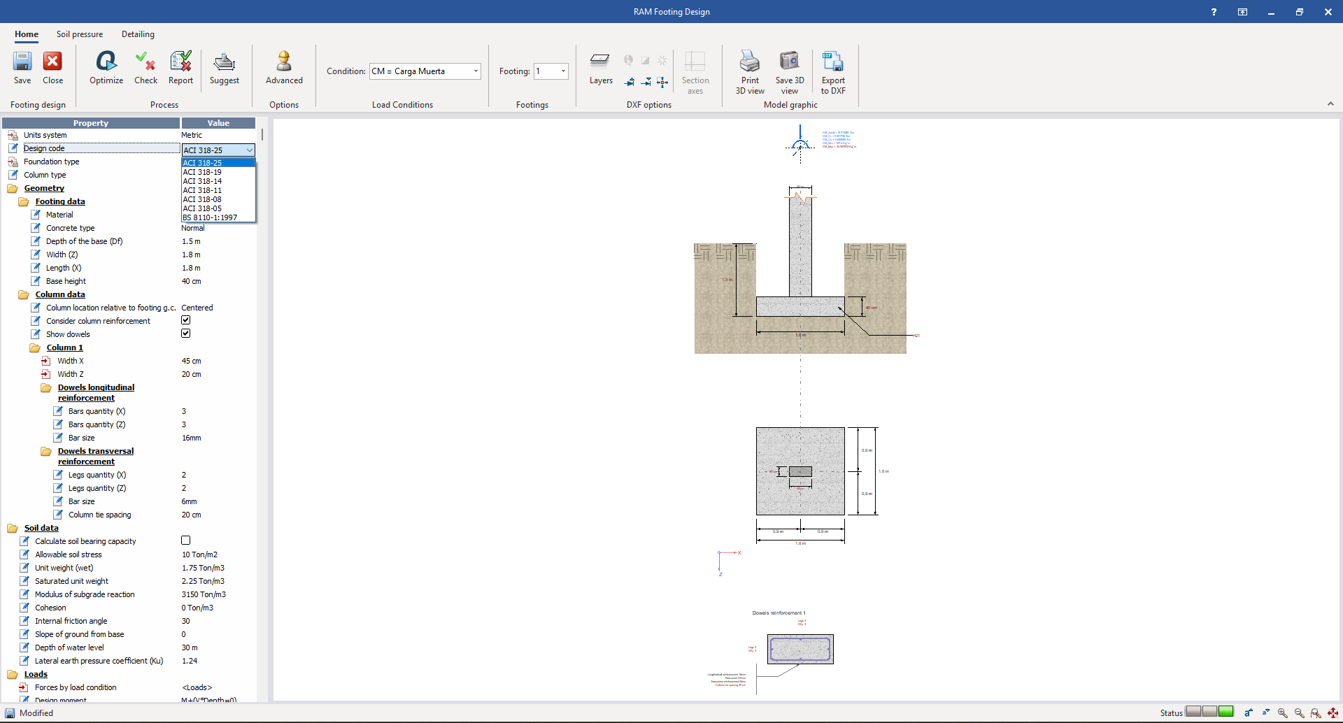
Figure 2. New ACI 318-25 concrete design code in the Footing Design module.
ACI 318-25 refines several strength provisions to improve design consistency. The shear strength equations were revised to restore capacity in members affected by size-effect reductions in ACI 318-19, particularly for walls and footings. Seismic wall provisions were adjusted to reduce excessive conservatism in high-ductility designs. Updates to development length and φ-factors improve anchorage predictions. Notably, the φ-factor for flexural compression now varies with axial load, producing smoother and more realistic P–M interaction curves near balanced point for columns and compression-controlled members.
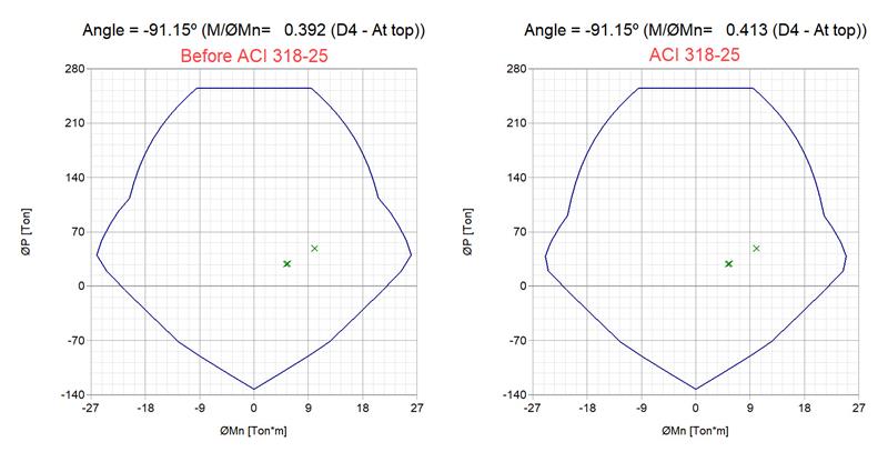
Figure 3. Changes in the flexural compression zone in the P-M interaction curve
2. Update AISI S100-2024 Cold-Formed Steel Design. RAM Elements now supports the AISI S100-2024 Specification for the Design of Cold-Formed Steel Structural Members, expanding the program’s alignment with the most current standards for cold-formed design.
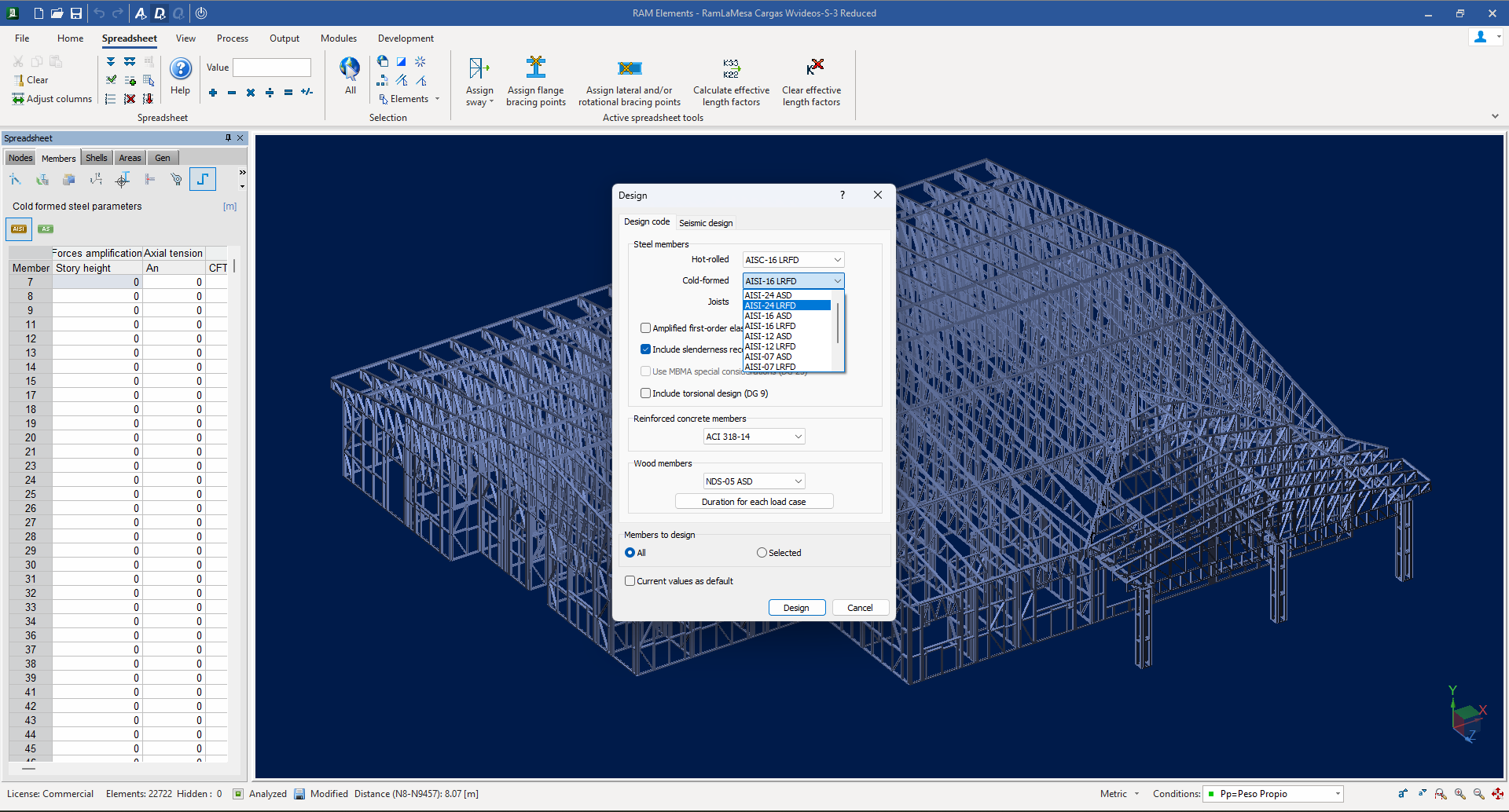
Figure 4. Update AISI S100-2024 Steel Cold Formed member design.
This update also extends cold-formed steel design capabilities to the Beam Design and Truss Design modules.
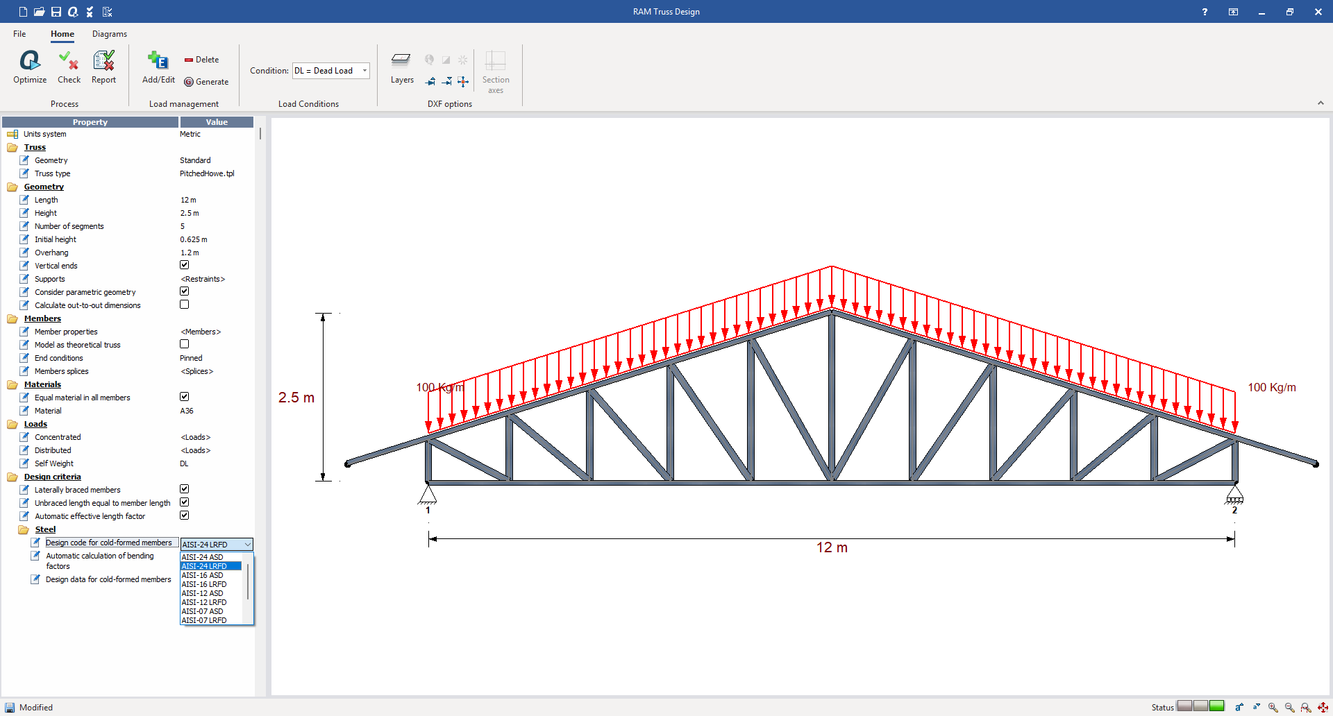
Figure 5. Update AISI S100-2024 Steel Cold Formed member design in the Truss Design module.
The implementation of AISI S100-2024 updates the cold-formed steel design framework to a force-based approach for flexural, torsional, and flexural-torsional buckling, replacing the previous stress-based method. The revision also introduces new equations for flexural-torsional buckling of asymmetric sections, improving the accuracy of stability checks for non-symmetric members.
Additional changes include new provisions for distortional buckling in flexure about the minor axis and revised equations for nominal distortional buckling strength, now based on the plastic moment instead of the elastic section modulus. The shear strength and reduction factor formulations were also updated, providing consistency with the new force-based design philosophy and reflecting a more unified treatment of strength across all limit states.
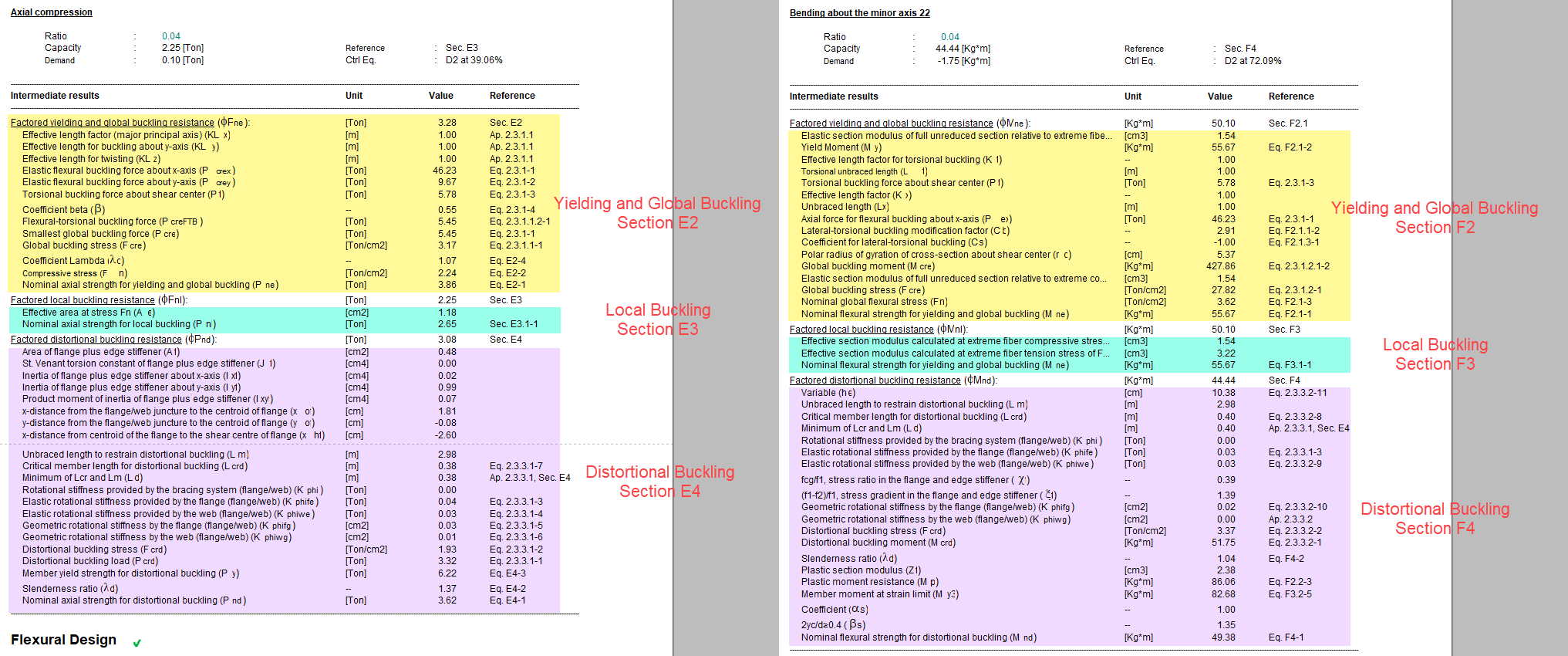
Figure 6. Enhanced report section showing intermediate results for compression and bending.
3. ASCE 7-22 Wind Load Definitions Generator. This release introduces an enhanced Wind Load Generator that now supports ASCE 7-22 definitions for wind loads. The Wind Load Definition dialog has been updated to allow users to select among different ASCE standards (ASCE 7-16, and ASCE 7-22), providing greater flexibility when defining parameters.
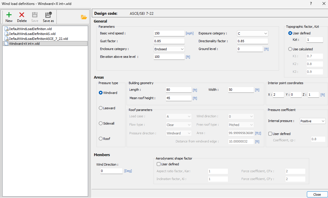
Figure 7. New ASCE 7-22 wind load definition
The implementation includes all required updates to generate wind loads on both areas and members incorporating revised pressure coefficients, exposure categories, etc. consistent with the ASCE 7-22 standard.
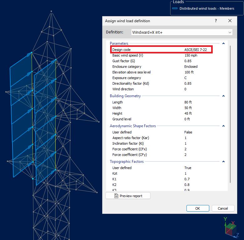
Figure 8. New ASCE 7-22 wind load generated over members.
4. Wall Modules Distribution of Stress at Openings Enhancement. Following improvements to the force integration routine in the wall modules, certain models were exhibiting higher stress ratios near discontinuities such as openings. These peaks are caused by stress singularities that occur at sharp geometry transitions and are now more accurately captured by the refined integration scheme.
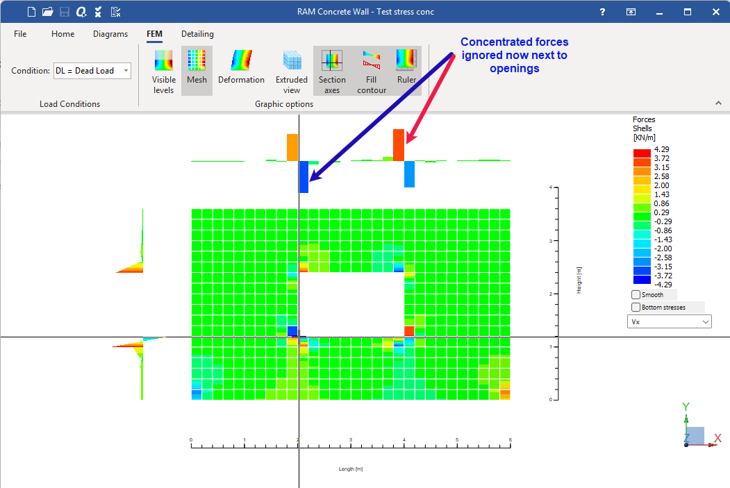
Figure 8. Concentrated forces near openings
To address this, the extreme FEM elements around openings are now intentionally skipped during the evaluation of out-of-plane shear. These edge elements often experience localized stiffness and mesh effects that do not represent the actual structural behavior. By excluding them, the results provide a smoother and more realistic shear distribution across the wall panel, minimizing noise and eliminating artificial stress concentrations near opening boundaries. The technique aligns with classic findings in computational mechanics on stress concentration (e.g. see Xie et al.)
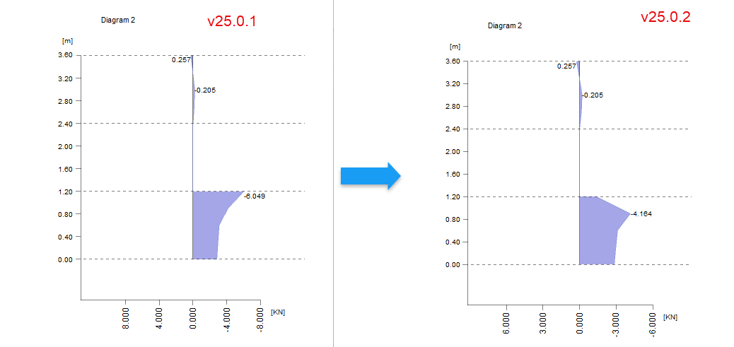
Figure 9. Concentrated forces near openings fixed to prevent unreal higher stresses
This approach ensures that the reported forces better reflect the global behavior of the wall, while maintaining the improved numerical precision introduced by the updated integration method.
5. New Scaffold Base Support Tool: A new tool has been added for the analysis of temporary scaffolding structures. Scaffoldings are temporary systems supported directly on the floor. The new feature allows users to model this behavior accurately by defining compression-only base supports. This approach prevents unrealistic uplift reactions and provides a more realistic distribution of vertical forces under gravity and lateral loads.
Figure 10. New scaffold base supports tool to define base supports.
6. Area Loads in OpenRE: The OpenRE XML format used to create and exchange RAM Elements models now supports area load definitions. Users can now create OpenRE files that include area loads or save RAM Elements models with existing area loads, improving interoperability.
7. New “Fit Texts” Option for Reports: Some report tabs contain text strings that are longer than the available tab space, making them difficult to read or causing misalignment. The new Fit Text to Tab option allows users to control how these long strings are displayed in report tabs. Users can now choose whether to trim the text to fit within the tab width for a clean, compact layout, or to display the full text, allowing the tab to expand dynamically as needed. This option improves the readability and layout flexibility of generated reports.
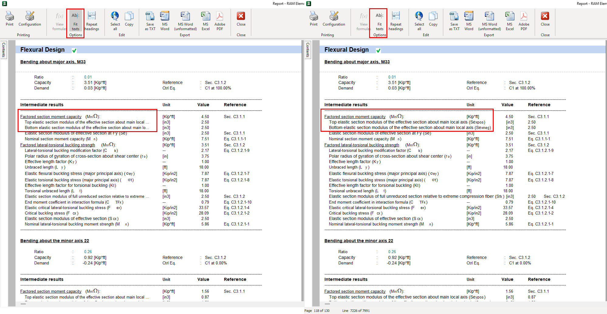
Figure 11. “Fit Texts” option applied to the same report, showing trimmed and full string displays
Resolved Issues:
Duplicated Nodes Causing Incorrect Reactions and Base Shear in Response Spectrum Analysis: When a model contained duplicated nodes (same coordinates but different IDs), the Response Spectrum analysis produced incorrect reactions and base shear results because node IDs were mismatched between the user model and the internal RAMFE analysis model. The fix updates the post-processing routine to correctly map reactions and basal forces when RAMFE consolidates nodes with identical coordinates, ensuring consistent and accurate reporting. (1699150)
Masonry Module – Lintel Design Direction Reversed: The lintel design routine applied an incorrect sign convention for the resisting moment, which caused reinforcement to be placed on the wrong face of the lintel. The fix corrects the sign interpretation so that negative moments now properly produce bottom reinforcement placement, consistent with lintel design conventions. (1709773)
PLAXIS–RAM Elements Integration Error: During the import of analysis results from PLAXIS, data transfer errors prevented the successful exchange of model information. The integration process has been updated to properly validate, read, and map PLAXIS output data into RAM Elements, restoring full interoperability between both applications. (1726540)
Shear Wall Grouting Factor for Partially Grouted Walls with 8" Spacing: For masonry shear walls defined as partially grouted with 8-inch spacing, the program did not classify them as fully grouted, resulting in underestimated design strength. The design logic now treats walls with 8-inch spacing as fully grouted, aligning program behavior with masonry design practice. (1733215)
Inconsistent Steel Design Results Between Main Screen and Design Report: Differences were observed between design ratios shown in the main window and those in the detailed report. This has been fixed synchronizing results across all views. (1754450)
AISI S100 Web Crippling Not Calculated with the Correct Web Thickness for Custom Sections: For custom sections with elements with different thicknesses, the web crippling capacity was considering the element with the maximum slenderness ratio regardless of if it was a flange or a web resulting in conservative capacity values. The calculation has been updated to correctly identify and use the thickness of the web element with the maximum slenderness ratio. (1701598)
AISI S100 Shear Capacity Not Calculated with the Appropriate Web Thickness for Custom Sections with Several Webs: When analyzing custom sections composed of multiple webs with different thicknesses, the shear capacity was calculated using a single web thickness associated with the element of maximum slenderness. This has been fixed, and the shear capacity is considering all webs, using its corresponding thickness and shear area to obtain the total section capacity. (1709769)