| Applies To | |||
| Product(s): | OpenPlant Isometrics Manager | ||
| Version(s): | 08.11.09.XXX | ||
| Environment: | Windows 7 64 bit | ||
| Area: | Settings/Attributes | ||
| Subarea: | - | ||
| Original Author: | Keith Couvillion, Bentley Technical Support Group | ||
Symbology
The Component Placement section in the Configuration Manager controls the color, line style and line weight of piping and components in the drawing.
-
Open Bentley Project Administrator V8i
-
Select your project in the Browser Tree
-
Click OpenPLANT Isometrics
-
Click Settings
-
Click Create/Modify
This opens the OpenPLANT Configuration Manager -
Click the Isometrics Style tab
-
Select the relevant style from the “Style” option button
-
From the categories in the left pane, select “Component Placement”
-
Change any of the symbology configuration options and click “Save”
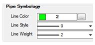
Pipe Symbology
Use the steps below to set the symbology for pipe and bend components.
-
Open the Isometrics Configuration tool
-
From the Isometric Configuration dialog:
- Select the Isometrics Style tab
- Style – Select the relevant style from the dropdown
- Select Component Placement from the tree
- Pipe Symbology – Set the Line properties as required
- Click Save
Use the step below to change the level (layer) for pipe and bends.
-
Select a level name from the drop down list
OR
-
Type a new level name in the text box. The new level will be added to the drawing during creation.
-
Click Save

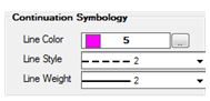
Continuation Symbology
Use the steps below to set the symbology for continuation components.
-
Open the Isometrics Configuration tool
-
From the Isometric Configuration dialog:
- Select the Isometrics Style tab
- Style – Select the relevant style from the dropdown
- Select Component Placement from the tree
- Continuation Symbology – Set the Line properties as required
- Click Save
Existing Pipework Symbology
Use the steps below to set the symbology for existing components.
-
Open the Isometrics Configuration tool
-
From the Isometric Configuration dialog:
- Select the Isometrics Style tab
- Style – Select the relevant style from the dropdown
- Select Component Placement from the tree
- Dotted Pipework Symbology – Set the Line properties as required
- Click Save

Failed Components Symbology
Sometimes components cannot be drawn in the iso. Most commonly this is due to a missing symbol in the cell library or an incorrect or missing mapping in the Supplemental Isometrics Isoextractor schema. The location of the failing components in the isometric drawing is indicated with a thick red circle. To change the symbology, set color, line style and line weight according to your preferences.
-
Open the Isometrics Configuration tool
-
From the Isometric Configuration dialog:
- Select the Isometrics Style tab
- Style – Select the relevant style from the dropdown
- Select Component Placement from the tree
- Failed Cell Symbology – Set the Line properties as required
- Click Save

See Also
communities.bentley.com/.../12641.modifying-the-iso-content
Comments or Corrections?
Bentley's Technical Support Group requests that you please confine any comments you have on this Wiki entry to this "Comments or Corrections?" section. THANK YOU!