| Applies To | |||
| Product(s): | AutoPIPE | ||
| Version(s): | 2004, XM, V8i, CONNECT; | ||
| Environment: | N/A | ||
| Area: | |||
| Subarea: | |||
| Original Author: | Bentley Technical Support Group | ||
| Date Logged & Current Version | June. 2016 10.01.00.09 | ||
Problem:
How to define distances of the nozzles relative to the center line of equipment when Rotating Equipment module through reference points and rigid elements in AutoPIPE?
Solution:
Think of the Tools> Rotating Equipment command as a separate application that only takes data from the Rotating Equipment dialog.
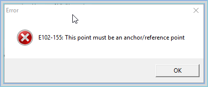
Open the Rotating equipment dialog, these node point names must be either an anchor or reference node name. It does not matter if there is rigid properties assigned to the piping.
Entering any other type of node point that is not one these types will automatically display the following message:
 See link here
Before using Rotating Equipment command, make sure that your node point to be used in the Rotating Equipment dialog all have Anchors or all assigned with Reference points. This is easy to confirm by using the Input Grids (Review Component Data), select the Anchor tab & Reference Point tab to confim node points appear in the respective listings.
Note: If there are known manufacturer loads then it is best to use Reference points
For pumps we give the user a way to input resolution point (or pump center, the pump center is defined relative to the suction nozzle). AutoPIPE does not have that kind of input requirement for turbines or compressors.
See Also
External Links
Bentley Technical Support KnowledgeBase
Comments or Corrections?
Bentley's Technical Support Group requests that you please submit any comments you have on this Wiki article to
the "Comments" area below. THANK YOU!