So, you have ProjectWise and you are using the spatial features. You have background maps. You know how to assign the spatial location to you new files. What about all those existing drawings that you want to assign a spatial location to? Here is an explanation of how easy it is to build your own custom way of assigning spatial location to fit your needs. You will be able to apply MicroStation VBA to the ProjectWise “Scan Spatial Locations…” tool.
You will learn how to edit the macro and then use it to scan some DGN files. Running the scanner is also covered. MicroStation and ProjectWise V8i are required.
The example MicroStation VBA file included with the install of ProjectWise Explorer named CustomExtract.mvba is slightly modified here to include additional options. The base functionality of CustomExtract.mvba is to scan the DGN for the first shape element that has a graphic group number of 100 and send its verticies to the scanner for assignment of the spatial location. The lines added to this example show how simple it is to modify the program to fit other needs. Some example .mvba files are available here in the Files tab to scan forarcs, points, shapes, and shapes in all attached reference files.
NOTE: As of March 2011, If the number of verticies exceeds 165, the scanning process will fail to generate a spatial location. There is a Change Request on this.
First: Open CustomExtract.mvba in the MicroStation VBA editor.
- Navigate to: C:\Program Files\Bentley\ProjectWise\bin\V811 folder. For 64 bit OS: C:\Program Files (x86)\Bentley\ProjectWise\bin\v811
- Select and then Open CustomExtract.mvba
- With CustomExtract selected click the Visual Basic Editor tool.

The code displays in the VBA editor where you can revise the code.
Edit the code
First read the comments (in green) to understand what code should and should NOT be edited. I reccomend you copy the line of code to be edited and paste it just below, place a single quote (') before the original, making it a comment, and edit the copied line.
A simple change that could be made is to scan for something other than a shape element.
Goto the code section shown below and remove everything after oScanCriteria including the ".". Then enter a "." and all the valid choices are presented as shown below.

To add one of the displayed options to the code double click.
To scan for an element type other than shape - delete only msdElementTypeShape. Upon entering a space after oScanCriteria.IncludeType, a list of valid element types is presented as shown below.
To add one of the options, again, just double click.
Shown below is some code that could be used to select only an element that is of a specific color, level name, linestyle, or line weight. Just comment out the line If .GraphicGroup = 8 Then and un-comment one of the other lines.

Only one item can be uncommented in the above code. to meet multiple attrubutes you can follow the example below.

NOTE: to test against a level name the level object must be defined first using Set oLevel = .Level.
Using elements with out verticies
The example code will only work with elements that have verticies, like shape, linestring, line. If you scan for an element type that does not have verticies more code must be revised. All graphic elements have a range property. Instead of assigning the spatial location per the verticies of an element it can be assigned to the four corners of the elements extent by using the range property.
Just comment out all the code used to get and assign the verticies (shown with three single quotes) and insert code to assign the range values per below. This example 'looks' for msdElementTypeArc.

With the editing complete the code must be debugged and tested.
Debug the Code
Better save the changes made so far.
To debug, a DGN must be opened which contains an element of the type and attributes the code is looking for. You can switch to MicroStation and add an element. Simply use the minimize window button to get back to MicroStation. When done, Alt-tab to go back to the VBA editor
Some of the code won't run outside of the Scan Spatial Locations... tool and must be turned into comments so that it is not evaluated. Make it easy to identify code that must be un-commented before actual use of the application in testing. For example, simply use five (') marks as shown below. This code must be commented out.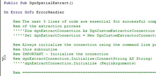
Additional code must be commented out. Near the end of the user editable section, add comments to
' ' ' ' ' dgnExtractConnection.AddPoint vertex.X, vertex.Y, vertex.Z
and finally below the user editable section
' ' ' ' ' dgnExtractConnection.Terminate
One way to debug is to place the cursor just before a line of code and run the program to the cursor. It stops there.
Place the cursor before:
max = .AsVertexList.VerticesCount - 1
From the Debug menu select Run To Cursor.
If the line of code turns yellow, debugging has stopped and you know the preceding code is valid.
You can continue to process the code line by line using F8.
To stop click the reset button designated by a blue square icon.
When done, don't forget to delete the five single quotes to un-comment all the code needed for the program to run.
Test the code and Scan for Spatial Location
Be sure to save any changes made to the code.
Exit and then restart MicroStation with any DGN not in ProjectWise. If MicroStation is NOT running when the scanner uses an MVBA scanning project, an error is thrown, yet it does successfully complete. There is TR on this. MicroStation can be minimized.
Start ProjectWise. Be sure the DGN you want to scan is in ProjectWise.
From the ProjectWise menu select Tools, Scan Spatial Locations...
Select Next on the Wizard information dialog.
Select the DGN(s) that have the particular shape element in it. Use the Select Individual files tool to select the file or files to scan.
Select the files and just click OK. The Add button is used to add the files you have selected and then select more files from other folders.
Files do not have to be checked, and if they are it will have no effect. Individual files are always scanned. Reading the note at the bottom of the dialog, the check box only applies to folders. Refer to ProjectWise Explorer Help > Contents > Using ProjectWise Spatial Tools > Spatial Scanning and Loading > Spatial Location Scanning > To run the Spatial Location Import tool for details.
Click Next.

If the DGN(s) do not have a Geographic Coordinate System (GCS) the Extract Location Onlyoption must be used. Then select the appropriate GCS from the list.
If the DGN(s) have a GCS, you can select the Extract Location and Coordinate Systemoption to add the GCS to those already in ProjectWise Explorer. Refer to ProjectWise ExplorerHelp > Contents > Using ProjecWise Spatial Tools > Spatial Location Scanning > Extract Location Only versus Extract Location and Coordinate System for details on how this works.
Click the Advanced command button.
In the MicroStation Scanner Options form, if references are attached to any of the selected DGNs they can be included in the scan process.
Select one of the Geometry types: Minimum Bounding Rectangel (MBR) generates a square representing the spatial location, Convex Hull generates a shape, or use theOrientated Rectangle option.
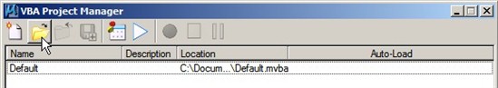
Select the Folder icon to select the MVBA Scanning Project to test.
Click OK to accept options
With the options set, click Next
The Logging Options can be left blank or defined as desired. Click Next.
With the spatial location configuration complete, click the Start Scan command button to start the process. When complete, a results dialog will display the statistics of the completed process.
Click the Exit button to close the wizard.
Observe the results using the ProjectWise Explorer Spatial or Geospatial tab.