| Applies To | |||
| Product(s): | AutoPIPE, | ||
| Version(s): | 2004, XM, & V8i | ||
| Environment: | N/A | ||
| Area: | Modeling | ||
| Original Author: | Bentley Technical Support Group |
Tutorial - Ring Main Wizard
Product: AutoPIPE
Version Number: 9.6.1
Submitted By: JT
Revision: 0.0
Introduction
AutoPIPE can only place one mid-point on a bend element, making ring creation difficult. The Ring Main Wizard is AutoPIPE’s solution to easily model ring mains for pipe stress analysis. A ring main is constructed of bends (Angles) and short runs of straight pipe (Header Length) between each successive bend (Angle) elements. Additional nodes / connection points can be inserted on these short runs of straight pipe (Header).
The purpose of this tutorial is to explain the new capabilities of the ring main wizard. New fields introduced will be covered, as well as how the geometry is automatically generated after accepting the changes in the wizard dialog.
Further Information
For further information on how to insert ring mains to a pipe sections, refer to AutoPIPE’s online help:
Help > Contents> Contents Tab> Command Reference> Insert & Modify Commands> Component Reference> Ring
In addition, a complete printable PDF of this information will be available after installing AutoPIPE V8i 09.06.01.xx and higher in the following file:
C:\Bentley\AutoPIPE V8i SELECTseries5\Documents\Tutorial - Ring Main Wizard.pdf
New Inputs in AutoPIPE v9.6
A new menu item has been created that opens the Ring Main Wizard dialog (Insert > Ring). This new dialog makes generating a piping ring main for models convenient and quick to duplicate.
Example #1: Create a Circular Tee-Branch Ring
Open the WALKTHRU Model
Open the WALKTHRU.DAT model located under the Examples folder of the AutoPIPE install directory. Before continuing, save this model as WALKTHRU_Ring.dat.
Select the Appropriate Point and Open the Ring Main Wizard
Select point B04 as the active point. Open the Ring Main Wizard dialog (Insert > Ring).
AutoPIPE automatically sets the offset point to the active point, B04. The Ring Orientation field rotates the plane that intersects all point on the ring about the directional axis. Set this to 0.0 degrees. Check the Close Ring checkbox. This will generate a closed ring by generating a new segment on the last bend. Set the DY Offset field to 3.0 feet, which means that the center of the pipe will be +3 feet along the Y-axis from point B04. Set Branch Type to Tee. Note that new fields become available; set Tee offset type to Radial, leave Pipe identifier set to 8SCH40, and for Tee Branch Offsets settings check the Radial Outwards radio button in addition set Length = 1.0 ft. This will generate a tee pipe on each point of the ring main facing outward radially from the center of the ring by 1 foot. Click Next button at the bottom to continue.
Define the Ring Type, Branch Type and Branch Properties
Set Ring Type to Circular Ring and note the available option on the dialog.
In the Circular Ring section, select Number of Angles radio button and set the Number of Angles to 4 (number of successive bends used to create the ring main). The Header field determines the run length of each ring point, with the midpoint being the ring point. Leave this at 0.00 ft.

View Data, pressing this button will display all the component and locations automatically calculated by AutoPIPE based on the settings entered from the 2 dialog screens.
Click the Finish button to create the ring main.
View the segments generated through the Show Options dialog (View > Show Options). Select Segments option and click OK. Note that each tee has its own segment, as well as the last piping point in the ring (noted by dark green). This is done to close the ring on itself.
Warning: For radially outward tees on rings connected to the existing model, the last radial tee generated will also create “Tee Branch Offset” piping (Segment G) that overlaps the initial segment creating the ring main (Segment B). To remove this segment if it is unneeded:
1. Press Select> Segment
2. Press Select button to highlight the selection red and press the Finish button.
3. With Segment G selected, press Delete> Segment
4. When prompted: “Delete Segment, Please Confirm:”, press Yes button to complete the operation.
5. The extra segment has been removed.
Example #2: Create a Polygon Run-Branch Ring
Open the WALKTHRU Model
Open the WALKTHRU.DAT model located under the Examples folder of the AutoPIPE install directory. Before continuing, save this model as WALKTHRU_Ring.dat.
Select the Appropriate Point and Open the Ring Main Wizard
Select point A10 as the active point. Open the Ring Main Wizard dialog (Insert > Ring).
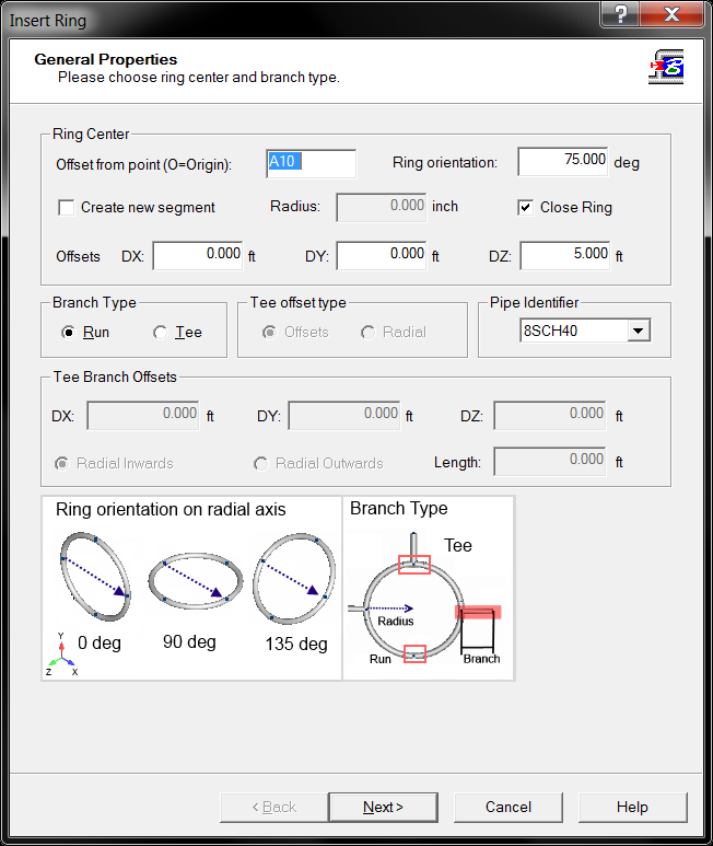
AutoPIPE automatically sets the offset point to the active point, A10. The Ring Orientation field rotates the plane that intersects all point on the ring about the directional axis; set this to value to 75.0 degrees. Check the Close Ring checkbox. This will create a closed ring main by generating a new segment on the last run. Set the DZ Offset field to 5.0 feet. This sets the center of the ring +5 feet along the Z-axis from point A10. Since this ring is connected to the rest of the model, AutoPIPE will set the ring radius to the offset. Leave Branch Type set to Run and Pipe Identifier set to 8SCH40. Click Next button on the dialog to continue to the next dialog screen.
Define the Ring Type, Branch Type and Branch Properties
Set the Ring Type radio button to Polygon Ring. Note depending on the Ring Type radio button selection the images update and certain fields become available. Number of Faces determines the number of sides that the polygon ring will have; leave this setting as 6 (default).
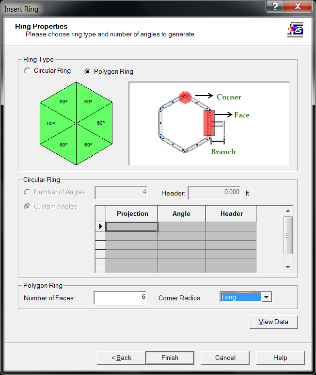
The Corner Radius has 4 different settings in a dropdown listing that relates to the bend size at the corners of the polygon ring when the main is created. Change this dropdown to Long.
View Data, pressing this button will display all the component and locations automatically calculated by AutoPIPE based on the settings entered from the 2 dialog screens.
Click the Finish button to create the ring main.
Note: Ring Orientation causes the main to be rotated 75.0 deg counterclockwise from local vertical alignment or 0.0 deg orientation.
Open the Show Options dialog (select View > Show Options) and select the Segments radio button in the Color Plots tab. Click OK to see how segments are generated in the ring.
Since AutoPIPE cannot connect a segment onto itself, in order to create closed rings AutoPIPE generates a new segment for the last corner of the ring, representing a closed loop. This is also done for circular rings.
Example 3: Concentric Ring Example
Open the WALKTHRU model
With the basics understood, example 3 will create a complex model with two rings concentric of each other. Open the WALKTHRU model located under the Examples folder of the AutoPIPE install directory. Before continuing, save this model as WALKTHRU_Ring.dat.
Create First Ring
Select point B04 as the active point. Open the Ring Main Wizard dialog (Insert > Ring).
AutoPIPE automatically sets the offset point to the active point, B04. The Ring Orientation field rotates the plane that intersects all point on the ring about the directional axis; set this to value to 0.0 degrees. Check the Close Ring checkbox. This will create a closed ring main by generating a new segment on the last run. Set the DY Offset field to 10.0 feet. This sets the center of the ring +10 feet along the Y-axis from point B04. Since this ring is connected to the rest of the model, AutoPIPE will set the ring radius to the offset. Leave Branch Type set to Run and Pipe Identifier set to 8SCH40. Click Next button on the dialog to continue to the next dialog screen.
On the Ring Properties page, set up a Circular ring with Custom Angles
Since this ring is connected to the model, the projections here start at the connection of the ring to the model, point B04. Each projection around the ring ends a bend and creates a header run, in feet (meters). These projections are absolute to the angle of the original point, where relative angles are automatically derived by AutoPIPE. Fill in the data as shown in the table below.
Warning: Entering a table set that does not contain a 360.00 projection entry will create an unclosed ring, regardless if the Close Ring box on the General Properties page is checked.
Check Create new segment, which will create a ring initially detached from the existing model, which will be attached later. The Radius field becomes available, and will be set to 7 feet. Enter 84 inches. In order for this ring to be concentric to the existing ring, leave the offset at 10 feet from B04 on the +Y axis. Click Next. Note on the Ring Properties field that all of the information for the first ring is still available. Click Next to keep these inputs the same.
Connecting Concentric Rings
In this section, the two rings will be connected through the radial tees created on the smaller concentric ring. This is done by selecting the ends of each radial tee on the smaller ring (F01, G01, H01, I01, J01 and K01) and opening the Run dialog (Insert > Run). Set the Name of point to the corresponding run on the larger ring (B09, B13, B17, B21, B25 and B04 respectively). AutoPIPE will automatically enter the offsets for these runs.
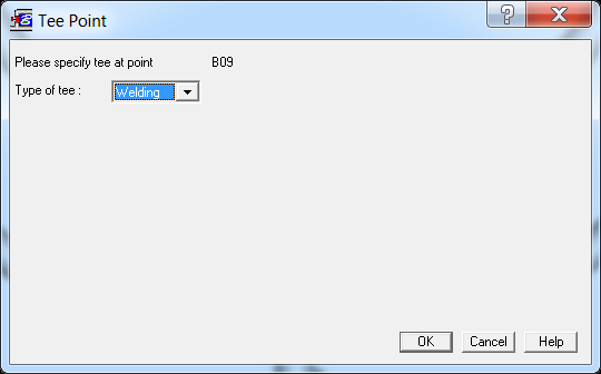
Enter the preferred tee type (Welding for all):
Warning: The tee created at B04 will prompt a warning, since a tee already exists at this point. To resolve this, select B04 and open the modify Tee dialog (Modify > Tee). Set the Tee component field to Cross.
Miscellaneous Information
Duplicating Ring Mains
The ring main wizard remembers the most recent settings created by the user. If the created model requires multiple ring mains of the same geometric properties, generate those ring mains first, before moving on to a new, unique ring main.
Add Support or Flange locations on Ring Main
As already known, AutoPIPE uses back to back bends and short straight runs to generate a ring main. Also known, supports can only be placed at a bend's Near, Far, or Mid points. Supports cannot be placed at a bend's TIP point. Here is one suggestion of precisely locating support locations on a ring main, Bend Mid points:
1. Generate a ring main utilizing AutoPIPE's Ring Main Wizard.
2. Next, save the AutoPIPE model, then use File> Export DGN or DXF
3. Open a cad application, (ex. Microstation, AutoCAD, etc..) and import the DGN or DXF file.
4. Accurately locate all support locations in the cad application.
5. Using an iterative approach, model those locations in AutoPIPE using a Bend's Mid point feature:
a. Measure in cad application from a reference point on the ring main to support location:
Example, reference point to support : DX = 0.000, DY = -5.889, DZ = -3.748, Dist = 6.980
b. From Cad, one knows approximately what bend the support location occurs, (ex. Bend KA09)
c. Edit the AutoPIPE bend, (ex. KA09) enable the Mid point check box, and enter a value for "Percentage around the bend"
Using simple deduction, the support occurs between the Near point (0%) and TIP point (50%) of the bend, Also appear to be a little more than half the distance (25%) between these 2 points, therefor first guess, set "Percentage around the bend" = 30 %
d. Using the measure tool, measure the offset from the Reference point to newly added bend Mid point (ex. KA09M).
Example: DX = 0.000, DY = -5.867, DZ = -3.702, Dist = 6.937
e. Continue iterating until offset matches cad measurement:
f. in less than 1 minute, found bend "Percentage around the bend" = 33% is a perfect match for the cad measurement.
g. Make bend mid point active (ex. KA09M), and insert support(s) / flange(s)as needed.
See Also