1. First step is to locate electrical dataset. From Workspace>Configuration look for variable BBESDATA. This variable points to electrical dataset.
2. Use windows explorer to navigate to electrical dataset (the location BBESDATA points to).
3. Locate Metadata folder under electrical dataset.
4. Using Notepad open File New_Panel_Schedule.PSF
5. Using Save As option save it as New_Panel_Schedule_84_poles.PSF
6. In New_Panel_Schedule_84_poles.PSF make following changes:
7. Change entry HowMany to 84 (new schedule has 84 poles)
[PHASE]
HowMany=84
Notice pattern of Cell definitions. Odd numbered Cells 1-83 stand for odd numbered circuits.
J,O and T stand for phases a,b and c.
8. Add additional entries after
Cell41=T28
As shown below:
Cell43=J29
Cell45=O30
Cell47=T31
Cell49=J32
Cell51=O33
Cell53=T34
Cell55=J35
Cell57=O36
Cell59=T37
Cell61=J38
Cell63=O39
Cell65=T40
Cell67=J41
Cell69=O42
Cell71=T43
Cell73=J44
Cell75=O45
Cell77=T46
Cell79=J47
Cell81=O48
Cell83=T49
9. Add additional entries after
Cell42=AK28
As shown below:
Even numbered Cells 2-84 stand for even numbered circuits.
Cell44=AA29
Cell46=AF30
Cell48=AK31
Cell50=AA32
Cell52=AF33
Cell54=AK34
Cell56=AA35
Cell58=AF36
Cell60=AK37
Cell62=AA38
Cell64=AF39
Cell66=AK40
Cell68=AA41
Cell70=AF42
Cell72=AK43
Cell74=AA44
Cell76=AF45
Cell78=AK46
Cell80=AA47
Cell82=AF48
Cell84=AK49
10. Under [DESCR] area change how many to 84
[DESCR]
HowMany=84
Description is actually Load description that is defined in Panel Manager.
11. Add additional entries after
Cell41=B28
As shown below:
Cell43=B29
Cell45=B30
Cell47=B31
Cell49=B32
Cell51=B33
Cell53=B34
Cell55=B35
Cell57=B36
Cell59=B37
Cell61=B38
Cell63=B39
Cell65=B40
Cell67=B41
Cell69=B42
Cell71=B43
Cell73=B44
Cell75=B45
Cell77=B46
Cell79=B47
Cell81=B48
Cell83=B49
12. Add additional entries after
Cell42=AR28
As Shown below:
Cell44=AR29
Cell46=AR30
Cell48=AR31
Cell50=AR32
Cell52=AR33
Cell54=AR34
Cell56=AR35
Cell58=AR36
Cell60=AR37
Cell62=AR38
Cell64=AR39
Cell66=AR40
Cell68=AR41
Cell70=AR42
Cell72=AR43
Cell74=AR44
Cell76=AR45
Cell78=AR46
Cell80=AR47
Cell82=AR48
Cell84=AR49
13. Change [TYPE] HowMany to 84
TYPE stands for load type defined in Load section in Symbol Manager. Purpose is to distinguish between different load types, for example, Lighting (L), receptacles (R), Motors (M)....
[TYPE]
HowMany=84
14. Add additional entries after
Cell41=Y28
As shown below:
Cell43=Y29
Cell45=Y30
Cell47=Y31
Cell49=Y32
Cell51=Y33
Cell53=Y34
Cell55=Y35
Cell57=Y36
Cell59=Y37
Cell61=Y38
Cell63=Y39
Cell65=Y40
Cell67=Y41
Cell69=Y42
Cell71=Y43
Cell73=Y44
Cell75=Y45
Cell77=Y46
Cell79=Y47
Cell81=Y48
Cell83=Y49
15. Add additional entries after
Cell42=Z28
As shown below:
Cell44=Z29
Cell46=Z30
Cell48=Z31
Cell50=Z32
Cell52=Z33
Cell54=Z34
Cell56=Z35
Cell58=Z36
Cell60=Z37
Cell62=Z38
Cell64=Z39
Cell66=Z40
Cell68=Z41
Cell70=Z42
Cell72=Z43
Cell74=Z44
Cell76=Z45
Cell78=Z46
Cell80=Z47
Cell82=Z48
Cell84=Z49
16. Change [POLES] HowMany to 84
[POLES} Stands for breaker poles 1,2 or 3. Breaker selection is part of circuit setup process in Panel Manager.
[POLES]
HowMany=84
17. Add additional entries after
Cell41=H28
As shown below:
Cell43=H29
Cell45=H30
Cell47=H31
Cell49=H32
Cell51=H33
Cell53=H34
Cell55=H35
Cell57=H36
Cell59=H37
Cell61=H38
Cell63=H39
Cell65=H40
Cell67=H41
Cell69=H42
Cell71=H43
Cell73=H44
Cell75=H45
Cell77=H46
Cell79=H47
Cell81=H48
Cell83=H49
18. Add additional entries after
Cell42=AQ28
As shown below:
Cell44=AQ29
Cell46=AQ30
Cell48=AQ31
Cell50=AQ32
Cell52=AQ33
Cell54=AQ34
Cell56=AQ35
Cell58=AQ36
Cell60=AQ37
Cell62=AQ38
Cell64=AQ39
Cell66=AQ40
Cell68=AQ41
Cell70=AQ42
Cell72=AQ43
Cell74=AQ44
Cell76=AQ45
Cell78=AQ46
Cell80=AQ47
Cell82=AQ48
Cell84=AQ49
19. Change entry [BREAKER] to HowMany=84 as shown below:
BREAKER] stands for breaker size. Breaker sizes are selected as part of circuit setup process in Panel Manager.
[BREAKER]
HowMany=84
[
20. Add additional entries after
Cell41=I28
As shown below:
Cell43=I29
Cell45=I30
Cell47=I31
Cell49=I32
Cell51=I33
Cell53=I34
Cell55=I35
Cell57=I36
Cell59=I37
Cell61=I38
Cell63=I39
Cell65=I40
Cell67=I41
Cell69=I42
Cell71=I43
Cell73=I44
Cell75=I45
Cell77=I46
Cell79=I47
Cell81=I48
Cell83=I49
21. Add additional entries after
Cell42=AP28
As shown below:
Cell44=AP29
Cell46=AP30
Cell48=AP31
Cell50=AP32
Cell52=AP33
Cell54=AP34
Cell56=AP35
Cell58=AP36
Cell60=AP37
Cell62=AP38
Cell64=AP39
Cell66=AP40
Cell68=AP41
Cell70=AP42
Cell72=AP43
Cell74=AP44
Cell76=AP45
Cell78=AP46
Cell80=AP47
Cell82=AP48
Cell84=AP49
22. This concludes changes to New_Panel_Schedule_84_poles.PSF . Save this file in Metadata folder.
23. Next step is to add excel template file that will be used for 84 pole panel schedule.
From Metadata folder open file NEW_PANEL_SCHEDULE.xls
24. Using File Save as option save this file as NEW_PANEL_SCHEDULE_84_POLES.xls
25. Add additional rows for circuits 43-84 to the existing schedule. Easiest way is to copy existing rows for circuits 1-42, paste it after circuit 42 and change numbers to reflect new circuits 43-84.
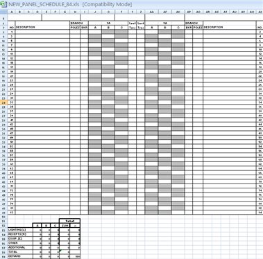
26. Excel spread sheet has formulas imbedded. Select option to view formulas and modify each to include additional rows 29-49.
27. For example existing formula for Lighting load in phase A is
=SUMIF($Y$8:$Y$28,"=L",J8:J28)+SUMIF($Z$8:$Z$28,"=L",AA8:AA28)
Change this to
=SUMIF($Y$8:$Y$49,"=L",J8:J49)+SUMIF($Z$8:$Z$49,"=L",AA8:AA49)
The only change we are making is changing previous number of rows 28 to new number of rows 49.
28. Change all remaining formulas and save NEW_PANEL_SCHEDULE_84_POLES.xls into metadata folder.
29. When generating panel schedules, (Electrical>Output>Panel Schedules L+P) new option New_Panel_Schedule_84_poles.PSF is now available. By selecting it, new 84 poles panel schedule will be generated using file NEW_PANEL_SCHEDULE_84_POLES.xls as template.
