| Product(s): |
WaterSight |
| Version(s): |
10.00. |
| Area: |
Documentation |
Minimum required data
In order to have the pumps dashboards with meaningful information, the minimum recommended data is the following:
- Flow signal for each pump or for the all pump station;
- Discharge pressure signal for each pump or for the all pump station OR level signal of the downstream tank;
- If flow and head is only available for the all pump station, then pump status signal for each pump is required (see more information below under section "Pump measurement VS Pump station measurement";
- Pump curves (flow-head and flow-efficiency);
- Information if pumps are variable speed or not (if they are variable speed, check below);
- If variable speed pump, speed signal and full speed value are required (see below more detail);
With this information it will be possible to show the head curves graphs (including the curve and calculated operating points), the efficiency curves graphs (including the curve and estimated operating points) and the power curves graphs (including the estimated operating points). Also estimated efficiencies for each pump are displayed.
Therefore having a power signal is not required, but instead is good to have as it will allow to more accurately calculate flow-efficiency operating points, the power-flow operating points and also each pump efficiency. Below is summarized the additional information that would be helpful to have (but not required):
- Suction pressure signal (it can be ignored or a suction signal can also be estimated using WaterGEMS - by creating a derived signal. If you have doubts, please reach to your Bentley contact);
- Power signal and curve;
- If variable speed pump, variable speed efficiency curve (if not provided, the user should assume a default value of 97%, see below more for more information)
- Sensors reference elevation (fill in the sensors template tab – if not provided WaterSight assumes that suction and pressure level signals are at the same reference elevation)
Calculating Pump Head
When calculating pump head, the following cases might exist:
- Discharge tank level and suction level available - for this case the reference elevation of both sensors is required (information filled in Admin >> sensors)
- Discharge pressure and suction pressure available - if reference elevation for both sensors is not provided, WaterSight assumes they are located at the same reference elevation (information filled in Admin >> sensors)
- Discharge tank level and suction pressure available - for this case the reference elevation of both sensors is required (information filled in Admin >> sensors)
- Discharge pressure and suction level available - for this case the reference elevation of both sensors is required (information filled in Admin >> sensors)
- Only discharge pressure available - in that case suction signal is ignored and assumed to be roughly 0 - for example the pump is roughly at the water level - and discharge pressure reference elevation is not required. It is also possible to estimate the suction pressure by creating a derived signal in WaterGEMS (in that case reach to your Bentley point of contact for more information). Note that suction pressure can only be ignored when the pump is located roughly at the same elevation as the water level.
- Only discharge tank level is available - in that case pump head is not calculated as there is not enough information.
Figures below illustrate the several cases:
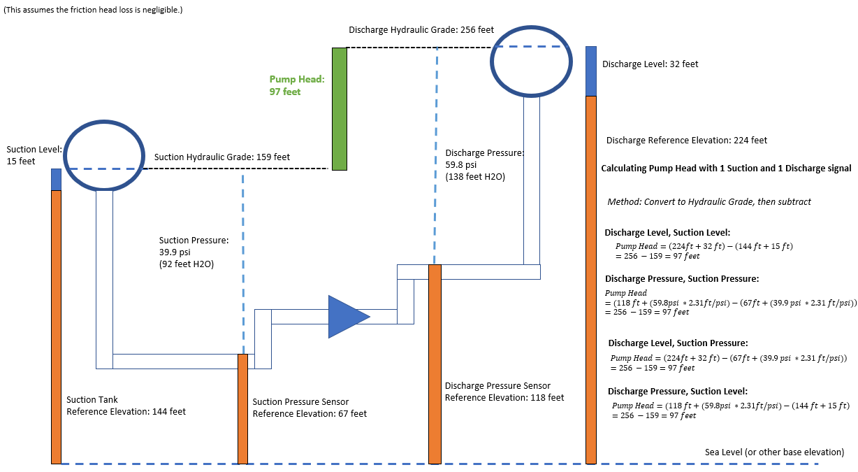
Figure 1 - Pump head calculation examples for use cases 1 to 4
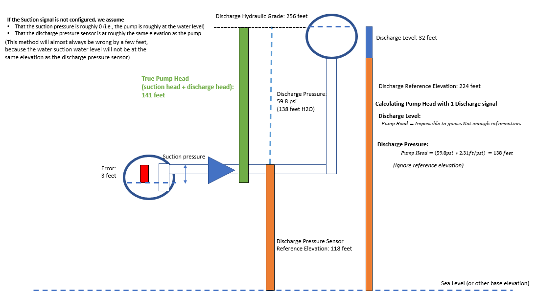
Figure 2 - Pump head calculation examples for use cases 5 to 6
Pump measurements VS Pump station measurements (flow-head operating points)
The following cases may exist:
- Sensor measurements are available for each pump (minimum required is pump flow and pump head);
- Sensor measurements are available at the pump station level (minimum required is pump station flow and pump station head) and status (on/off) is available for each individual pump;
1. Sensor measurements are available for each pump (minimum required is pump flow and head)
In case sensor measurements are available for each pump, flow and head operating points are accurately calculated (represented with blue dots in figure below). Head is calculated based on pump discharge pressure or downstream tank level and suction pressure (this last one is optional). It is not required to have a status signal for each pump in this case.
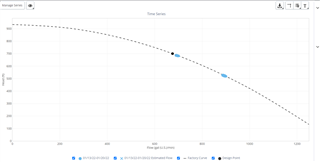
Figure 1 - Flow and head operating points based on actual measured pump flow and head (appearing as blue circles)
The pump signals configurations and other characteristics are done in the pumps administration page. Reference elevations for the associated pump sensors may also be required (information filled in Admin >> sensors).
For configuring case 1 above, the user just need to complete in the pump administration page the specific information and signals for each pump (configuration example below).
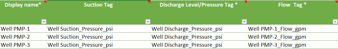
Figure 2 - Each pump has its own flow signal.
This first case also works if the pressure discharge signal is related to the all pump station, as long as the flow is available at each individual pump.
2. Sensor measurements are available at the pump station level
Flow and discharge pressure available for the all pump station
In case SCADA measurements are only available at the pump station level (for example total flow for the all pump station) then the pump status for each pump is required. If pump status for each individual pump is available, operating points for each pump can be estimated.
For the time-steps where at least two or more pumps are on simultaneously, the flow-head operating points for those pumps that are on will be estimated based on the total pump station flow and head (represented with blue crosses in figure below) and each pump flow-head curve (pump head curves are required).
Note: if pump status signal is not directly available for each pump but pressure discharge or flow is, then pump status can be indirectly inferred by creating a derived signal. More information below on section "Pump status - Signal Mapping.
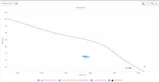
Figure 3 - Flow and head operating points estimated based on the total pump station flow and head (appearing as blue crosses)
For the time-steps where only one pump is turned on (and all other pumps are off), then it is assumed that the total pump station flow and head correspond to that specific pump that is on, and in this case flow-head operating points are accurately calculated (represented with blue dots in Figure below).
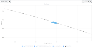
Figure 4- Pump Flow and head operating points are equal to the total pump station flow and head, in case only one pump is on (appearing as blue circles)
For configuring case 2, in the pumps administration page the user needs to assign for each pump:
- the the total station flow and head
- the specific status of each pump (configuration example below)
- plus the pump station information, including the flow-head curves, which are required.
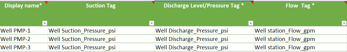
Figure 4 - Pumps share the same flow signal (assuming pumps in parallel). Please note that flow signal for each pump is the total station flow.
In case pump status for each individual pump is not available, the user can create a derived signal for status based on other individual pump signal such as power, discharge pressure or other. See below for more information. If status is not available neither can not be indirectly inferred, then it is not possible to calculate the information for each individual pump (in that case it is suggested to leave the pump flow and discharge pressure fields empty). In that case the analysis can be done through the pump station details page (make sure to fill the pump station information under the administration page).
Flow available for the all pump station and discharge pressure available for each pump
If pump station flow is available and discharge pressure for each individual pump, the pump status signal is still required as well as the suction pressure signal. Otherwise the flow operating points will not be correctly calculated (the individual flow for each pump is estimated based on the information of when each pump is on or off and the pump head curves). In case pump status for each individual pump is not available, the user can create a derived signal for status based on other individual pump signals such as power, discharge pressure or other. See below for more information. If status is not available neither can not be indirectly inferred, then it is not possible to calculate the information for each individual pump (in that case it is suggested to leave the pump flow and discharge pressure fields empty). In that case the analysis can be done through the pump station details page (make sure to fill the pump station information under the administration page).
If individual pump flow is available and discharge pressure is available for the all pump station, pump status information is not required (neither suction pressure).
For more information about interpreting the various pump curve graphs, click here.
Pump Efficiency Calculation
For both Variable Speed Pump (VSP) and non-VSP pumps, efficiency can be accurately calculated if power signal for each individual pump is available as well as the flow head-operating points (see above section about Pump measurements VS Pump station measurements).
For non-VSP pumps, and in case power signal is not available, then it is required to have the flow-head operating points (see above section) as well as the flow-efficiency curve for each pump.
For VSP pumps, and in case power signal is not available, then it is required to have the flow-head operating points (see above section), plus the flow-efficiency curve for each pump, plus the speed signal for each pump and the variable speed efficiency curve for each pump. If data related with the variable speed efficiency curve is not available, it is suggested to assume a fixed value of 97% of VFD efficiency for each value of motor speed.
Finally, and for any of the cases mentioned above, it is also suggested to insert the motor efficiency for each pump (typically a value between 90-95%) as the total efficiency displayed in the application is obtained by multiplying the pump efficiency by the motor efficiency (and speed efficiency in case of VSP pumps).
Variable Speed pumps additional data
For variable speed pumps, besides all the considerations mentioned above, and in order to display more meaningful information it is recommended to also include the speed signal and full speed value, besides the VSP efficiency curve (see above). With this additional information (and assuming that flow-head operating points as well as efficiencies are already available, see sections above) it is possible to visualize the normalized values and the different flow-head points for the different relative speeds.
More information about variable speed pumps can be seen here - Pump Details, under the section Variable Speed pumps.
Pump Status - Signal Mapping
As mentioned above, pump status signal for each pump is required in case there is no flow measurement at each individual pump, but only for the all pump station. In those cases the flow for each pump will be estimated based on each pump status signal and its curve. WaterSigth automatically assumes:
- pump is on if status raw values are equal to 1
- pump is off if status raw values are equal to 0
Pump status available
Only in case the pump status raw values are different than those mentioned above, it is a pre-requisite to previously map the pump status raw values. This is done at the sensor data pusher (OFOSC) level. The steps are described below.
1) Access the machine where the sensor data pusher (OFOSC) is installed
2) Go to services, and pause the Openflows Onsite Coordinator service
3) Open the WaterGEMS hydraulic model to be used by the OFOSC
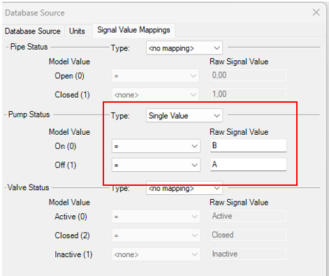
4) Go to Analysis >> SCADA Connect Simulator >> SCADA Signals. Click Edit on the Data source listed on the left and go to the tab "Signal Value Mappings". In the "pump status" section fill the raw signal values fields. In example below it is assumed that the pump is on when the raw values are equal to 70
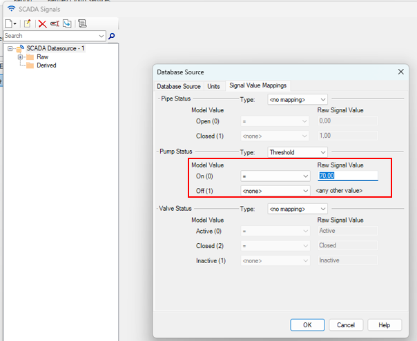
Figure 5 - Pump signal values mapping in WaterGEMS
5) if the pump stats raw signal is a string/text field make sure to select the type Single value and map to the right field.
6) The signal mapping for pump/valve/pipe status requires that the sensor data pusher can recognize that a signal is a pump/valve/pipe status signal. Therefore it is required to defined a SCADA element with the associated SCADA signal mapped to the model element. Create a SCADA element for each status signal and associate each SCADA element to a virtual pump. An example below (it is not required to have any hydraulic model defined).
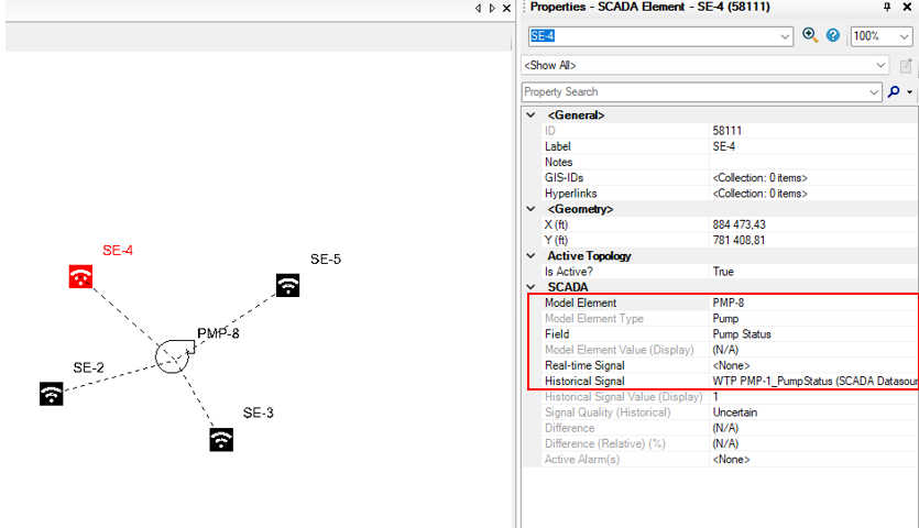
Figure 6 - Associate SCADA Signals to SCADA elements and SCADA elements to model elements (pump)
7) Save the WaterGEMS model inside the "Models" folder within the OpenFlowsOnsiteCoordinator folder
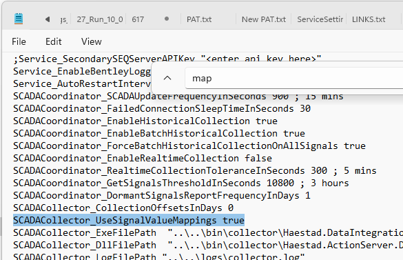
8) Access the OpenFlowsOnsiteCoordinator folder and open the "Settings.ini" file. Search for the field "SCADAColector_UseSignalValueMappings" and set it to true. Save the file.
9) Go to services and restart the OpenFlows OnsiteCoordinator service.
10) Confirm that the new status signals are already defined in WaterSight and the sensor tag in WaterSight matches the ones in WaterGEMS. To upload the new signals go to WaterSight >> Admin >> sensors and upload the new sensors. Go also to Admin >> pumps >> and assign the new pumps status sensors to the pumps.
Pump status not available but there is discharge pressure for each pump
If there is no pump status available at all for each pump but there is for example discharge pressure available for each individual pump it is suggested to create a derived signal for each pump status based on the discharge pressure values. This can be achieve using the if condition when creating the derived signal. Please make sure to convert the the values to 1 for the pump to be on and 0 for the pumps to be off. The steps are described below.
1) Access the machine where the sensor data pusher (OFOSC) is installed
2) Go to services, and pause the Openflows Onsite Coordinator service
3) Open the WaterGEMS hydraulic model to be used by the OFOSC
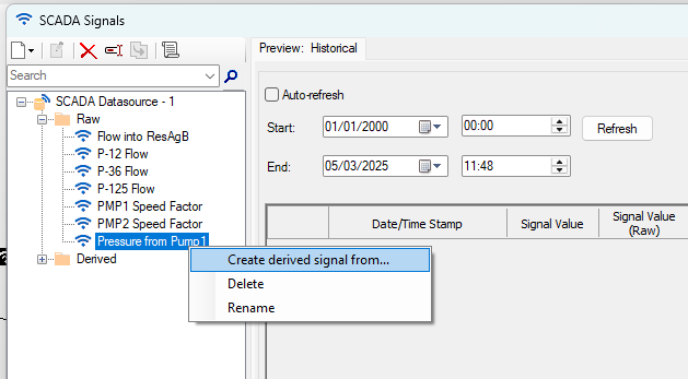
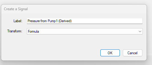
4) Go to Analysis >> SCADA Connect Simulator >> SCADA Signals. On the left side panel, right click on the discharge pressure sensor and select "Create derived signal from".
5) Select Transform method "Formula".
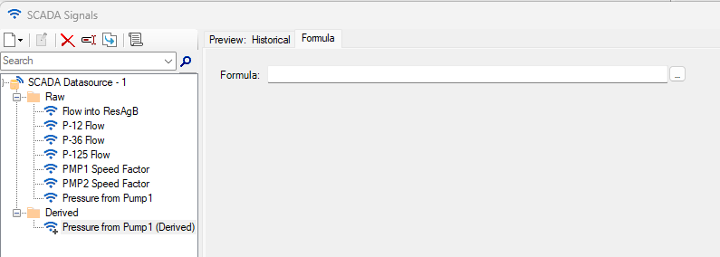
6) Select the derived signal on the left, go to Formula tab and click in the (...) button.
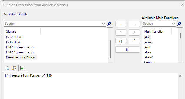
7) Create a "IF" condition. An example below - if pressure is above 1m, the signal value will be 1; otherwise will be 0. This will convert discharge pressure values in pump status of 0 (pump off) and 1 (pump on), and ready to be used by WaterSight.
8) Repeat steps 4 to 7 to each discharge pressure sensor
9) Save the WaterGEMS model inside the "Models" folder within the OpenFlowsOnsiteCoordinator folder
10) Go to services and restart the OpenFlows OnsiteCoordinator service.
11) Confirm that the new pump status derived signals are already defined in WaterSight (and the sensor tag in WaterSight matches the derived signal label in WaterGEMS). To upload the new signals go to WaterSight >> Admin >> sensors and upload the new sensors. Go also to Admin >> pumps >> and assign the new pumps status sensors to the pumps.
See also
Filling reference elevation for sensors - Admin sensors
Pump Details
Pumps Administration page
Prioritizing Pumps
OpenFlows WaterSight TechNotes and FAQ's
WaterSight Learning Resources Guide