for the staad foundation advanced, under the Slab Designer and you click the 'Design', a table of Moments and Rebar Area Required appears. if it says 'Failed' in Area required, do I need to increase the thickness? Kindly elaborate more on this. Thanks
RAM | STAAD Forum - Slab Designer in Staad Foundation Advanced

When you generate a moment envelope (default 60 X 60), the program is creating a grid of points on the surface of the mat. It fetches the moments along the longitudinal and transverse directions for each of those points by scanning through the results of all the ultimate load cases that the mat has been analysed for.
Then, at each of these envelope points, a total of 4 moments are fetched, each of which is the maximum value for that location from amongst all the ultimate load cases.
1. for longitudinal direction, tension on top surface of the mat
2. for longitudinal direction, tension on bottom surface of the mat
3. for transverse direction, tension on top surface of the mat
4. for transverse direction, tension on bottom surface of the mat
Note that each of these moments is per unit width of the slab, 1 metre or 1 foot, depending on the design code, which is what a FE analysis of a mat gives you.
Thus, for the purpose of flexure design, at each envelope point, the slab is treated as a beam having a unit width.
Next, the program calculates the maximum permissible moment on the cross section based on compression failure of concrete for the thickness at that location. So, if any of these 4 moments exceeds the maximum moment capacity of the section, then, that moment cannot be designed for, and that is when you get a fail in the design status report. Envelope points that fall directly under a column or a pedestal are not designed.
The moment capacity is based on the crushing of concrete, which if I am not mistaken is also associated with the maximum area of steel that the code permits for that thickness. So, changing the reinforcement arrangement isn't going to help. The only way to resolve it would be to increase the slab thickness. You may not need to increase it all over the slab, just find the areas of high moment and increase the thickness locally by creating regions of higher thickness in those areas.
Regarding your question on why such large steel areas are shown in the screenshot you attached, we need your model. Also, let us know what build of the program you are checking it with.
thanks for the response. but if I use the moments I can still get the bar spacing by just increasing the bar diameter. that's why I wonder why there is a need to increase the footing depth....
In these kind of situation increasing depth will help you.
Also, I noticed that the Rebar Area Required in the next column is quite big. How is it computed?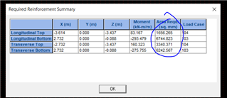
communities.bentley.com/.../mat-foundation-for-checking-0.55-thk.sfa Thanks a lot @Kris Sithia. see attached file for your reference.....previously it was .5m thickness but Rebar area failed in bottom reinforcements so I adjusted to .55m
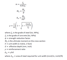
Procedure for calculating the area of steel for the ACI code
Procedure to upload an SFA file:
Procedure to upload a file if you want to keep it private : Secure File Upload
thanks for the reply Kris Sathia. I followed your instructions for the 0.5m thickness and below is what I got.....
this is the meshing after the run. Will it not affect the direction of the rebars?
when i clicked the Slab Thickness again, 3 thkness are added for each auto generated region
then I clicked the Soil Property and this what i saw...
I changed the zero values with 1.5 and analyze then I got the following result....
'Failed' is still appearing and now 3 are failed from previous 2. I was expecting not to see 'failed'...
Here are a few suggestions.
1) Edit the job and remove the primary load cases 1, 2 and 3 from the Selected Load cases list. Thus, the analysis and design should be just for cases 101 to 104, 201 and 202.
2) The screenshot of the "Required Reinforcement Summary" that you attached earlier indicates that 3 of the 4 locations - Long Bot, Trans Top and Trans Bot - are within the perimeter of the columns. The program is supposed to ignore points beneath columns but versions prior to 9.6 had a defect that caused such points to be designed. The "What's New" section for version 9.6 mentions this.
Upgrading to 9.6.1.74 is the logical answer. But if you cannot do that, try the following:
In the Meshing Setup page, there is an option known as "Auto Generate Control Regions for Columns". It will create regions each having the same dimension as the perimeter of the columns.
Select each of them one at a time, edit, and switch off the option called "Design Control Regions".
Re-mesh the mat. Re-analyze. Then perform the design again. It should ignore the points beneath the columns and the 0.5m thickness should pass.
thanks a lot for this explanation @Kris Sathia, just want also to know how the steel areas are calculated based from those moments? btw, how to send here my model?
thanks for the reply @Souvik Munshi.
Really? working with 9.6? I'm currently using version 9.3. May I know the moments that you got with 0.55m and 0.5m thickness? just want to know the difference between the two versions. TIA. This is wat I got with 0.5m thkness.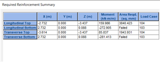
It is found that in latest released SFA version 9.6.1.74 the attached file is being designed successfully with 0.5 m thickness without any failure. Please let us know the SFA version number you are using.
For the model you attached, we
1) Removed load cases 1, 2 and 3 from the Selected Load Cases list.
2) Changed the slab thickness to 500 mm
3) Re-meshed the slab with a target maximum size of 500 mm
4) Analyzed the mat. Generated the envelope. Designed the slab.
Here are the results from 9.6.1.74
Thanks a lot @Kris Sathia for the comprehensive reply to my queries. Appreciate it!!
Btw, just want to verify if the moments computed by version 9.3 higher than the moments computed by version 9.6?
Also, the rebar areas that I got from version 9.3 are quite higher that if i compute it manually using the formula you've given above. Is version 9.6 giving an accurate rebars areas required? TIA.
It does appear that the slab design results are incorrect.
There were 3 releases of SFA since version 9.3. Over that period, all the errors reported by users and ones found by our internal testing in mat foundations have been corrected.
I would urge you to upgrade to the latest - 9.6.1.74. We have tested the results produced by this version for your model and are confident that they are correct.
Here is the answer to your other questions.
Meshing does not affect the direction of rebars. If you look in the Moment Envelope generation page, you will find the terms Longitudinal and Transverse, and those are defined over there as along global X and along global Z by default. After the analysis, when you generate the moment envelope, the program calculates the bending moments that are aligned with those directions. Reinforcement is calculated for those Long and Trans directions.
The region thicknesses can be changed if you wish. By default, the programs assigns them a thickness which is the same as that for the remainder of the mat. But if those have a higher thickness, you must enter them accordingly.
In the soil property page, it is best to leave the soil height as zero for Auto-generated regions. Those regions represent space occupied by columns, so it is not possible for soil to occupy that space, hence the reason for assigning a height of 0.
thanks a lot for the reply @Kris Sathia. seems that version 9.6 is more accurate.